Gateway Load Balancing Protocol
Sections:
- Lab Topology
- Group Numbers
- AVF vs AVG
- Base Configuration
- GLBP States
- Hello Packets
- Priority & Preemption
- Authentication
- Load Balancing Methods
- GLBP Timers
- GLBP Weighting Track
- Object Tracking
Overview:
- GLBP is a Cisco proprietary protocol standard designed to provide high network availability and redundancy for IP networks
- GLBP is utilized in Cisco networks to provide load balancing amongst multiple routers that share the same virtual IP address but each router using its own unique virtual MAC address. This allows GLBP to distribute traffic among the different routers in the group, which leads to better utilization of available network resources
- GLBP, HSRP, and VRRP all share similarities in features and command structure however there is some new terminology and concepts of the GLBP protocol that will be discussed
Lab Topology
In this lab scenario, we will configure the concepts of GLBP on Gateways R1 - R4.

Group Numbers
Group Numbers in GLBP represent the routers that are participating in a GLBP group. In GLBP, you can have up to 1023 groups. The interface serving as the default gateway for the clients on the network will be assigned a group number. Group numbers have to match between all routers that are part of the same GLBP group within the same VLAN or subnet.
HQ-Gateway-R1
GLBP group numbers.

AVF vs AVG
GLBP introduces new router roles such as the AVG and the AVF.
Active Virtual Gateway
The AVG or Active Virtual Gateway, is a active/standby role assigned to one of the routers in the GLBP group and is responsible for managing the virtual IP address of the group. The AVG allows for the distributing of the load between the participating routers via the load balancing mechanism. The AVG is responsible for responding to ARP requests from clients on the network with a AVF's virtual MAC address that will handle the client's traffic based on the configured load balancing method. The AVG also acts as an AVF to forward traffic for the vIP like any other router in the group. In a GLBP group, AVGs will be assigned in an active/standby pair.
Active Virtual Forwarder
The AVF or Active Virtual Forwarder, is a router in the GLBP group that is responsible for forwarding traffic destined for the virtual IP address that clients use as their default gateway. AVFs are assigned different virtual MAC addresses to distinguish them in the GLBP load balancing mechanism. If an AVF fails, the AVG can reassign its virtual MAC address to another AVF router in the GLBP group, ensuring continuous forwarding. All AVFs are placed in a listen state and act as a backup AVG in cases when the active or standby AVGs fail.
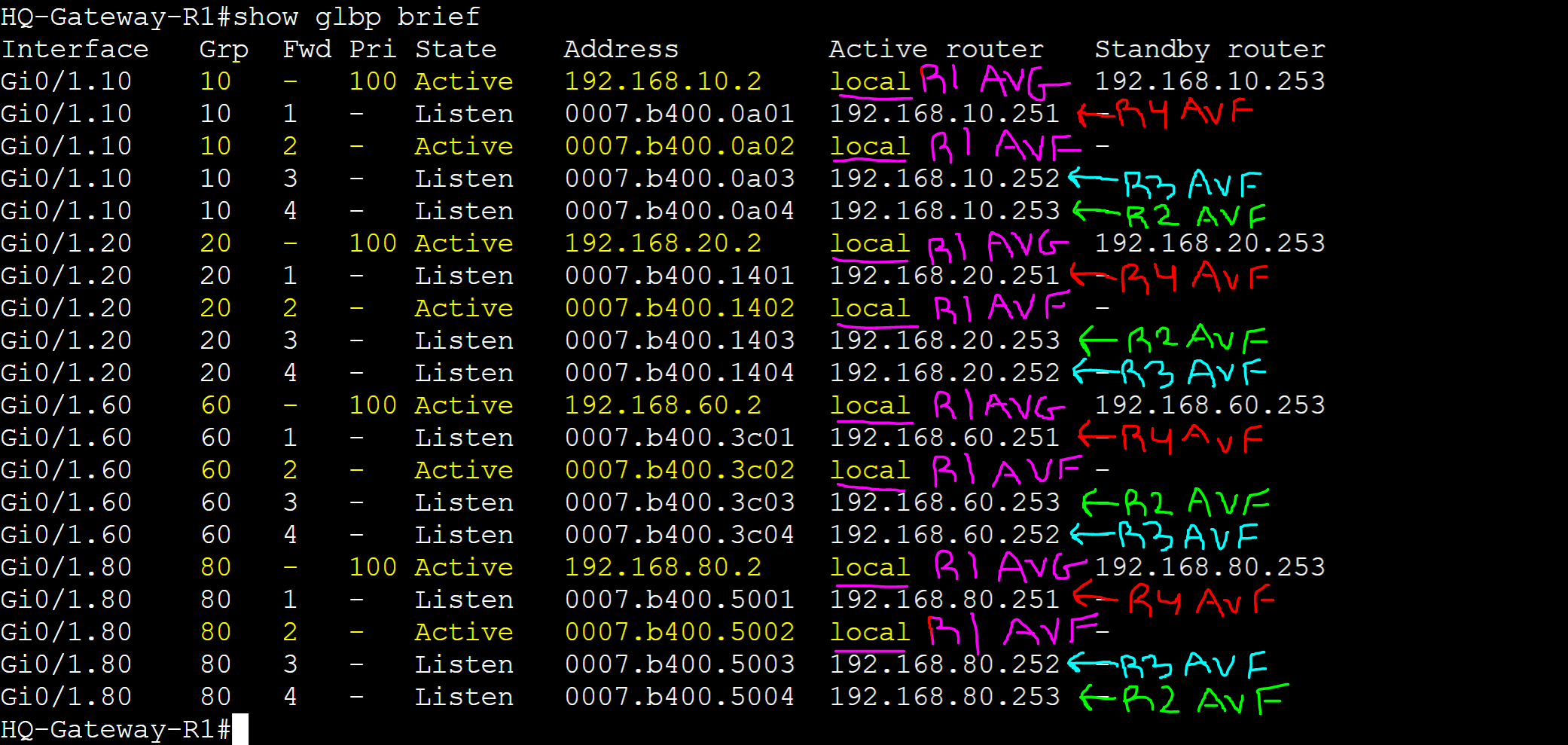
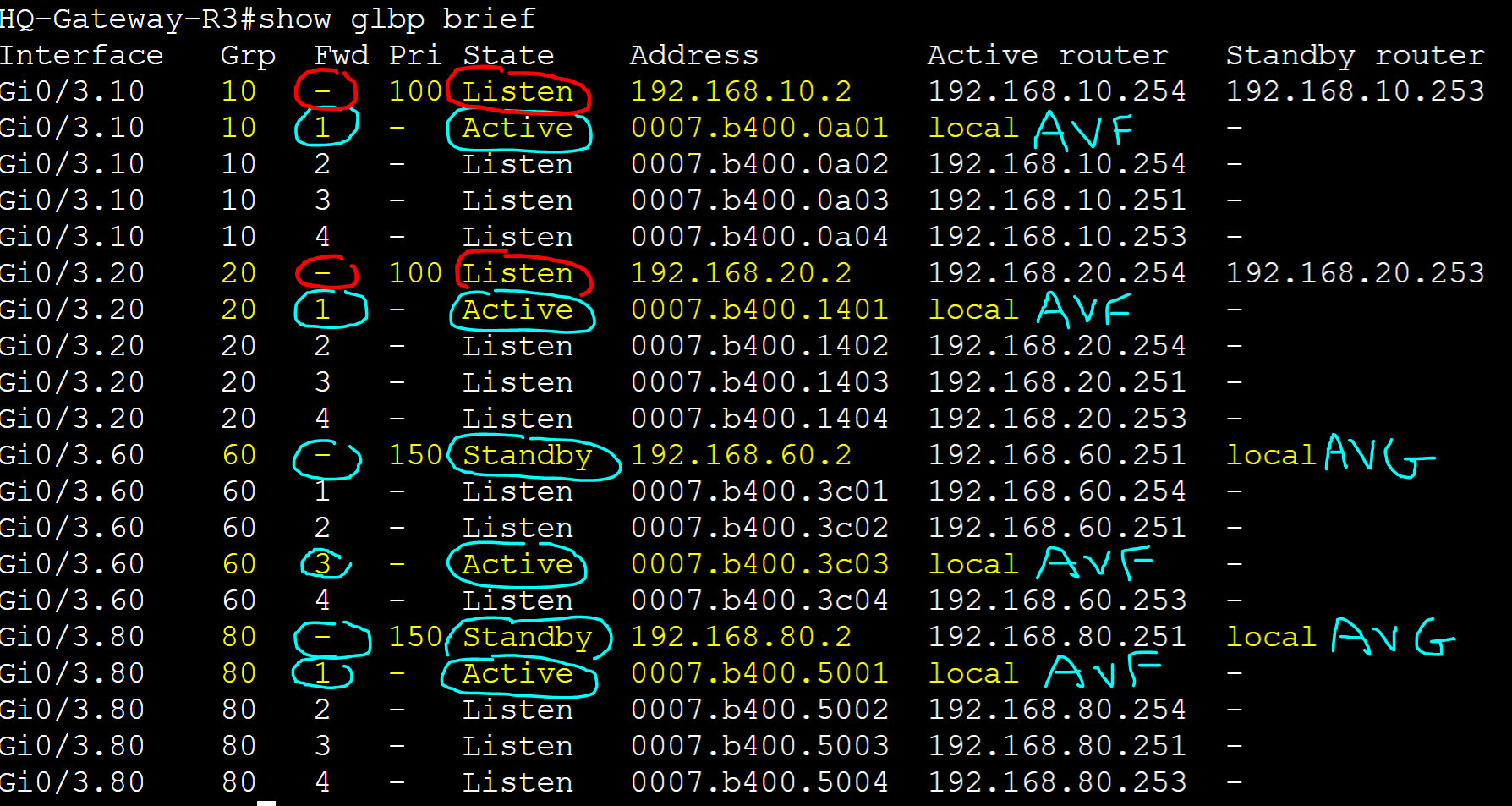
In this lab example, let's break down the AVF and AVG roles in the 'show glbp brief' command.
HQ-Gateway-R1 Group 10
Identify the AVG and AVFs for group 10.
In this GLBP topology there are 4 routers for groups 10 and 20. As the AVG also acts as an AVF, there will be a total of 4 AVFs and 1 AVG per group. In this example, we will analyze the AVG and AVFs for GLBP groups 10 and 20.
- The 'Fwd' identifier represents the AVF number. If it is blank, this indicates the AVG for the group. The active AVG for group 10 is 'local' or this router the command is being issued on. The standby AVG for group 10 is '192.168.10.253' representing Gateway-R2 in the lab topology
- To identify the AVF virtual MAC address of Gateway-R1 in group 10, look for an entry that consists of the following:
- A numeric AVF value in the "Fwd" field
- A state of active in the "State" field
- In this example the AVF virtual MAC address of Gateway-R1 in group 10 is '0007.b400.0a02' representing the local router. As a result, Gateway-R1 is the active AVG for group 10
- All other AVFs for a given group will be in the 'Listen' state serving as backup AVGs in case the active or standby AVG fails

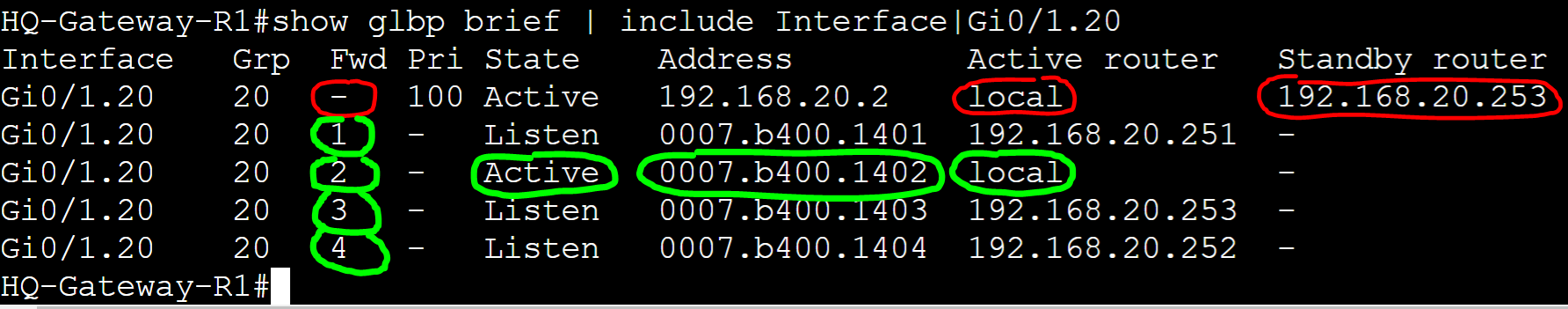
HQ-Gateway-R1 Group 20
Identify the AVG and AVFs for group 20.
In this example, the active AVG for group 20 is this local router (Gateway-R1) and the standby AVG representing '192.168.20.253' or Gateway-R2. The vMAC of AVF Gateway-R1 for group 20 is '0007.b400.1402'.
Summarize
To summarize identifying AVGs and AVFs in the 'show glbp brief' command, the AVG is responsible for responding to client ARP requests with an AVF vMAC for the vIP gateway of the group. The AVG also acts as an available AVF. There is an active and standby AVG for each group and can be manipulated by adjusting the group priority on each router. Out of all available AVFs, the active local AVF represents the local router you're issuing the command on. All AVFs will be in the 'Listen' state for the current active and standby AVG routers.
Base Configuration
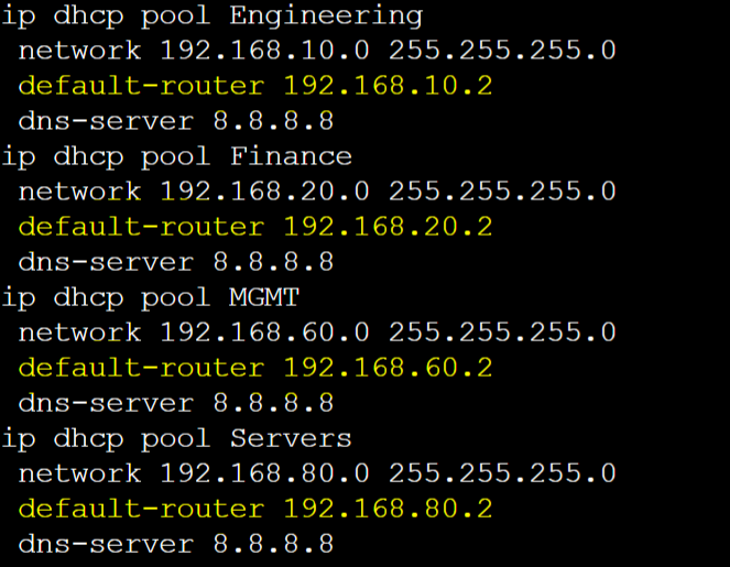
For this lab exercise, I will demonstrate a base configuration of GLBP with four routers each serving four groups for the VLANs 10,20,60, and 80. I have set and configured DHCP scopes on the Core switch for each VLAN and set the default gateway option to correspond to the appropriate GLBP VIP addresses of each group. The Virtual IP in GLBP is what logically allows routers in a GLBP group to work together to serve as the default gateway on the network. The VIP address must match between all routers in a group.
Unlike HSRP and VRRP, the virtual MAC address will be unique on all routers in the GLBP group to allow load balancing to work. All IP addresses need an associated MAC address in IP networking. GLBP uses the VMAC format '0007.b4xx.xxYY' where 'XX.XX' represents the GLBP group number in hexadecimal and the 'YY' representing the AVF number in hexadecimal.
HQ-Core-SW DHCP vIP
HQ-Gateway-R1 vIP

HQ-Gateway-R2 vIP

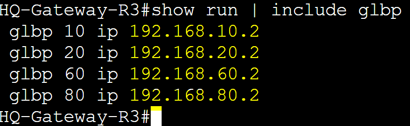
HQ-Gateway-R3 vIP
HQ-Gateway-R4 vIP

HQ-Gateway-R1 GLBP Base Configuration
HQ-Gateway-R1

Default configurations of GLBP consist of the following: Hello Timer: 3 seconds; Hold Timer: 10 seconds; Pre-emption disabled; Priority 100. The 'show glbp' command also lists the physical interface MAC addresses of each group member.
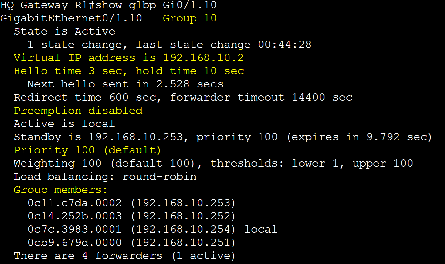
In the 'show glbp' command, all the AVFs for group 10 are listed in detail. AVF Gateway-R1 is Forwarder 2.

In the 'show glbp brief' command, Gateway-R1 is the active AVG for all of the groups and lists its vMAC for each group.

GLBP States
Similar to HSRP, GLBP routers go through a series of states used to determine it's role in the GLBP group.
GLBP States
- Init State: Router is waiting to start the GLBP process with the vIP known
- Listen State: vIP gateway is receiving hello packets and is ready to change to the 'speak' state if the active or standby AVG becomes unavailable
- Speak State: Router is attempting to become the active or standby AVG
- Active State: A router transitions into the active state if it is either selected as the AVF for a particular vMAC or is the active AVG
- Standby State: A router transitions into the standby state if it is next in line to be the active AVG
HQ-Gateway-R1


Hello Packets
Hello Packets are essential in GLBP as AVG routers in a group exchange these messages to the multicast address destined for all GLBP routers to share their information about the GLBP domain and as keepalives for GLBP failover. Hello packets contain key information about the domain and are sent once an interface is configured with a vIP and group number. Below are some key components of GLBP hello packets.
TLV Fields
- GLBP uses two TLV fields in hello packets
- TLV 28 consists of AVG information
- TLV 20 consists of AVF information
Default Timers
- Hello Timer: 3 seconds
- Hold Timer: 10 seconds
- Redirect Timer: 600 seconds
- Timeout Timer: 14400 seconds
Packet Type
- Uses multicast address 224.0.0.102 (All GLBP routers)
- Encapsulated in UDP packets with a source and destination port of 3222
- Only the active and standby AVG routers exchange hello packets in the GLBP domain
GLBP Hello Packet Capture

Priority and Preemption
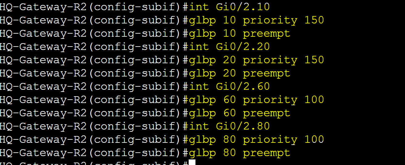
Priority is the value that determines which router in a GLBP group becomes the AVG router. The router with the highest priority becomes the active AVG router followed by the standby AVG. By default, all GLBP routers are set to the priority value of 100 and can be manually set in the range of 0-255. Pre-emption is disabled by default and can be enabled to allow higher priority routers to retake over the AVG role after a failure. In this lab example, for groups 60 and 80, I will adjust the priority value of Gateway-R4 to the highest value so it becomes the preferred active AVG router and a lower value on Gateway-R3 so it becomes the standby AVG. For groups 10 and 20, I will adjust the priority value of Gateway-R1 to the highest value for the active AVG role and a lower value on Gateway-R2 for the standby AVG. To demonstrate Pre-emption, if Gateway-R4 were to fail, Gateway-R3 will take over as the active AVG for groups 60 and 80. Once Gateway-R4 recovers from the failure, it would retake the active AVG role as its priority is configured to a higher value than Gateway-R3.
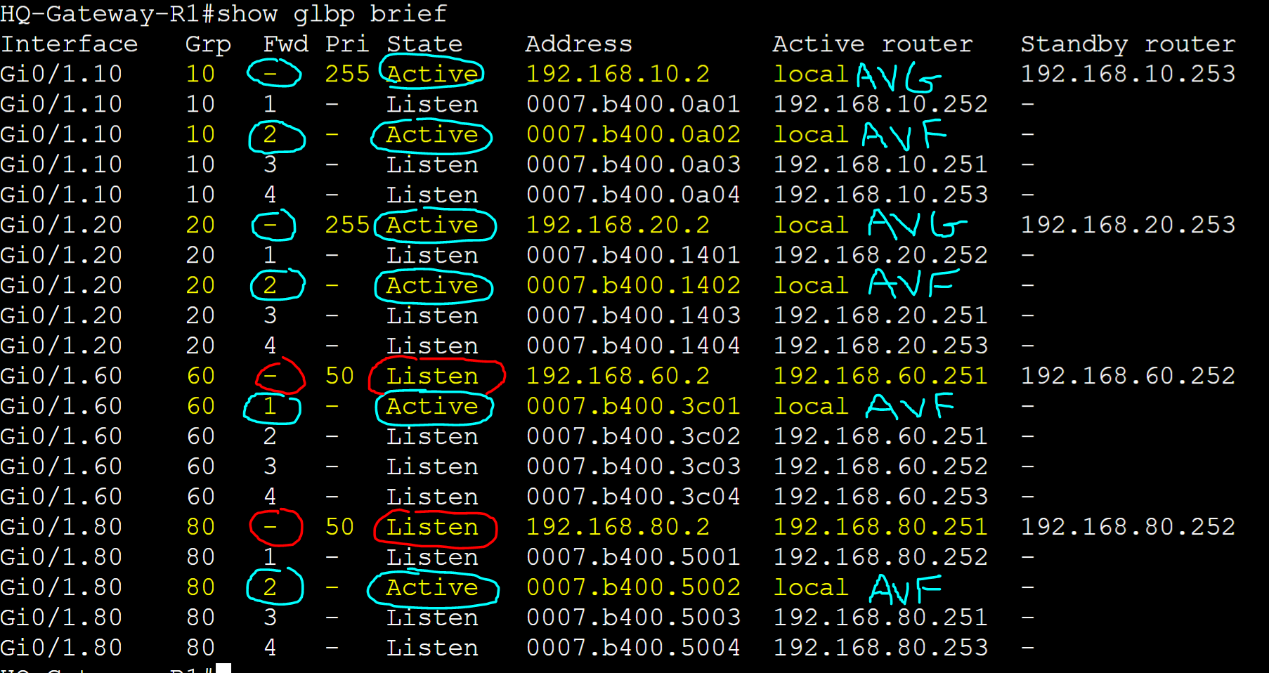
Router Roles (Groups 10/20)
- R1: Active AVG/AVF with Priority 255
- R2: Standby AVG/AVF with Priority 150
- R3: AVF with Priority 100
- R4: AVF with Priority 50
Router Roles (Groups 60/80)
- R1: AVF with Priority 50
- R2: AVF with Priority 100
- R3: Standby AVG/AVF with Priority 150
- R4: Active AVG/AVF with Priority 255
HQ-Gateway-R1
Base GLBP configuration on R1.

R1 is the active AVG for groups 10 and 20 and a standby AVG in the 'Listen' state to the current AVG active/standby pair for groups 60 and 80.
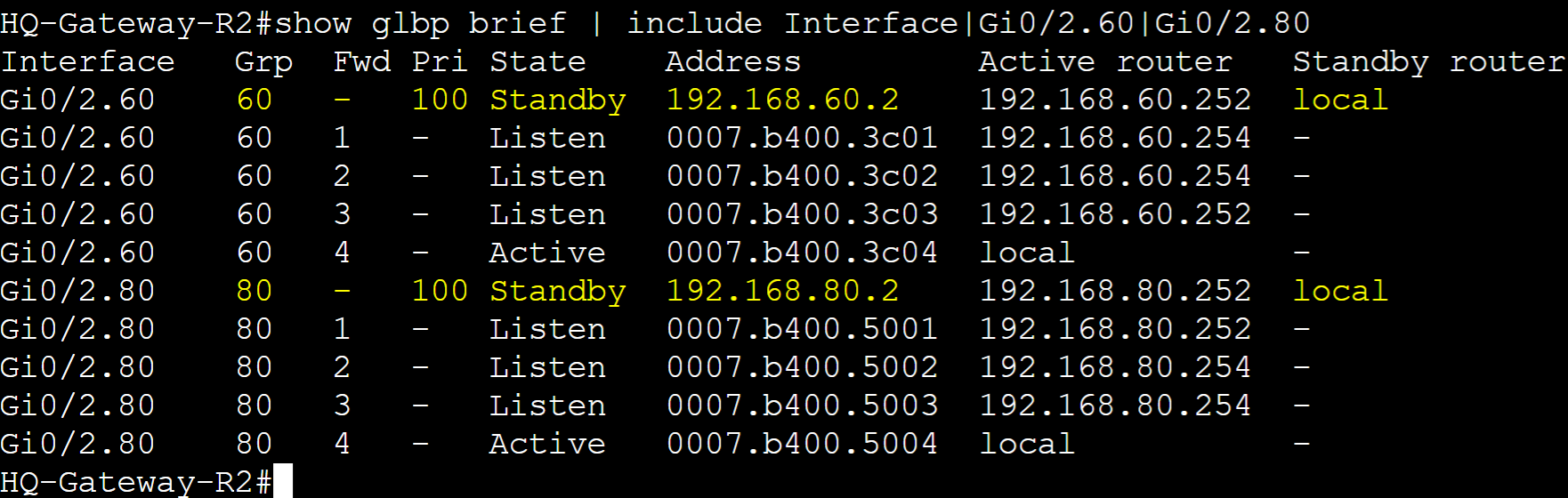
HQ-Gateway-R2
Base GLBP configuration on R2.
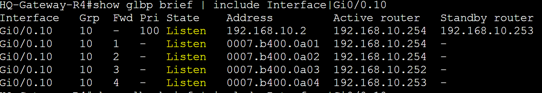
R2 is the standby AVG for groups 10 and 20 and a standby AVG in the 'Listen' state to the current AVG active/standby pair for groups 60 and 80.

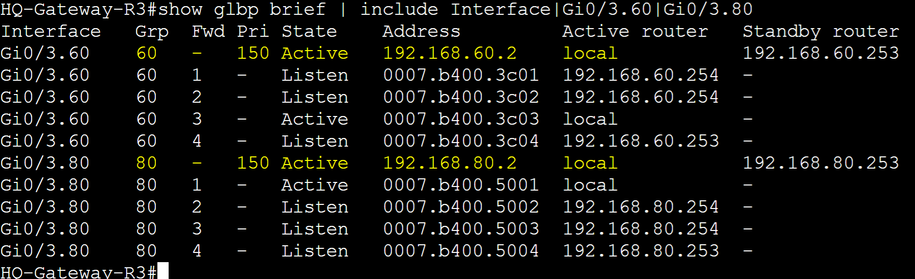
HQ-Gateway-R3
Base GLBP configuration on R3.

R3 is the standby AVG for groups 60 and 80 and a standby AVG in the 'Listen' state to the current AVG active/standby pair for groups 10 and 20.
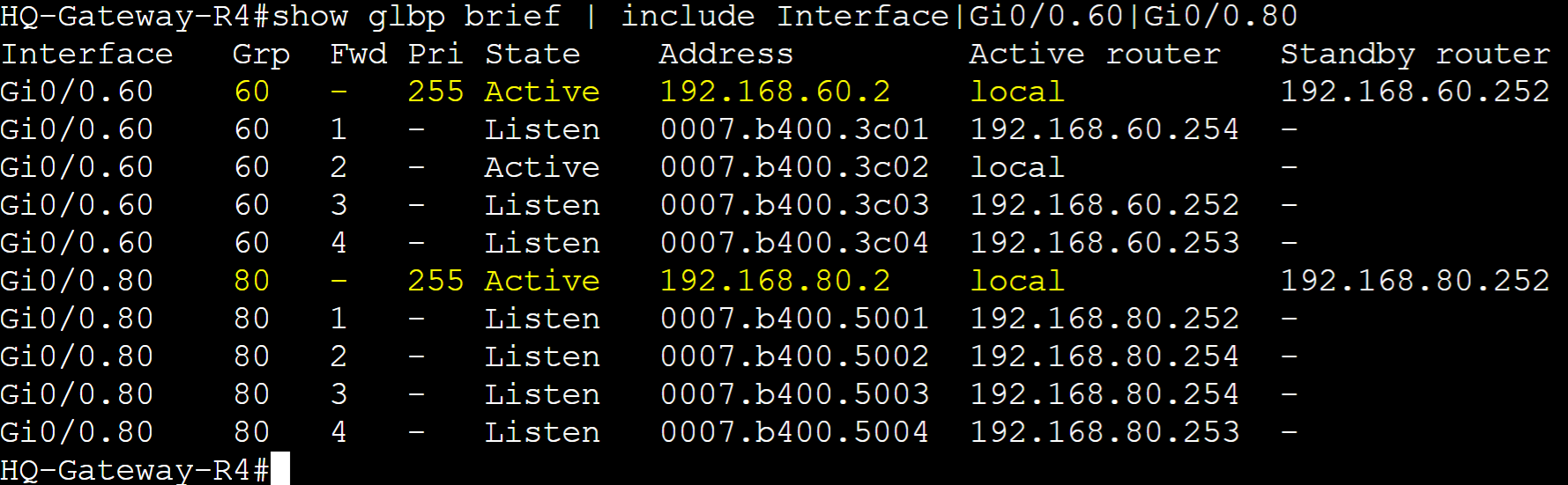
HQ-Gateway-R4
Base GLBP configuration on R4.

R4 is the active AVG for groups 60 and 80 and a standby AVG in the 'Listen' state to the current AVG active/standby pair for groups 10 and 20.

Pre-emption Failover
Demonstrated active AVG failure on Gateway-R4 for groups 60 and 80. Gateway-R3 transitioning to the new active AVG whereas Gateway-R2 transitions to a standby AVG.

Gateway R3 transitioning to the active AVG after the interface shutdown failure on R4.
Gateway R2 transitioning to a standby AVG after the interface shutdown failure on R4.
Gateway R4 transitioning back to the active AVG after R4 recovers via Preemption.
Authentication
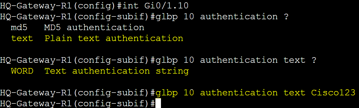
GLBP Authentication is an optional security feature that allows routers in a GLBP group to authenticate each other before participating in the protocol. This feature can prevent unauthorized devices from joining the GLBP domain. HSRP and GLBP use the same authentication method types including plain text and MD5 authentication. MD5 authentication is a cryptographic hash function that encrypts a plain text password and thus is more secure. In this lab example, I will configure Plain text and MD5 authentication in separate scenarios for the GLBP group 10 serving VLAN 10 on the network and then examine a packet capture with the authentication information included.
Plain Text Authentication
Gateway-R1
Gateway-R2

Gateway-R3

Gateway-R4

Authentication Troubleshooting
In cases where routers in a GLBP group are not joining the domain, you can issue the 'debug glbp errors' command on the router experiencing the issue to determine the cause. In this case, bad authentication is the concern and in this situation, the authentication string on R4 is incorrect.

Plain Text Packet Capture
Using Plain text authentication, a new TLV 16 authentication header is encapsulated in the GLBP hello packet.

MD5 Authentication
Gateway-R1

Gateway-R2

Gateway-R3

Gateway-R4

MD5 Packet Capture
Using MD5 authentication, a new TLV 20 authentication header is encapsulated in the GLBP hello packet.

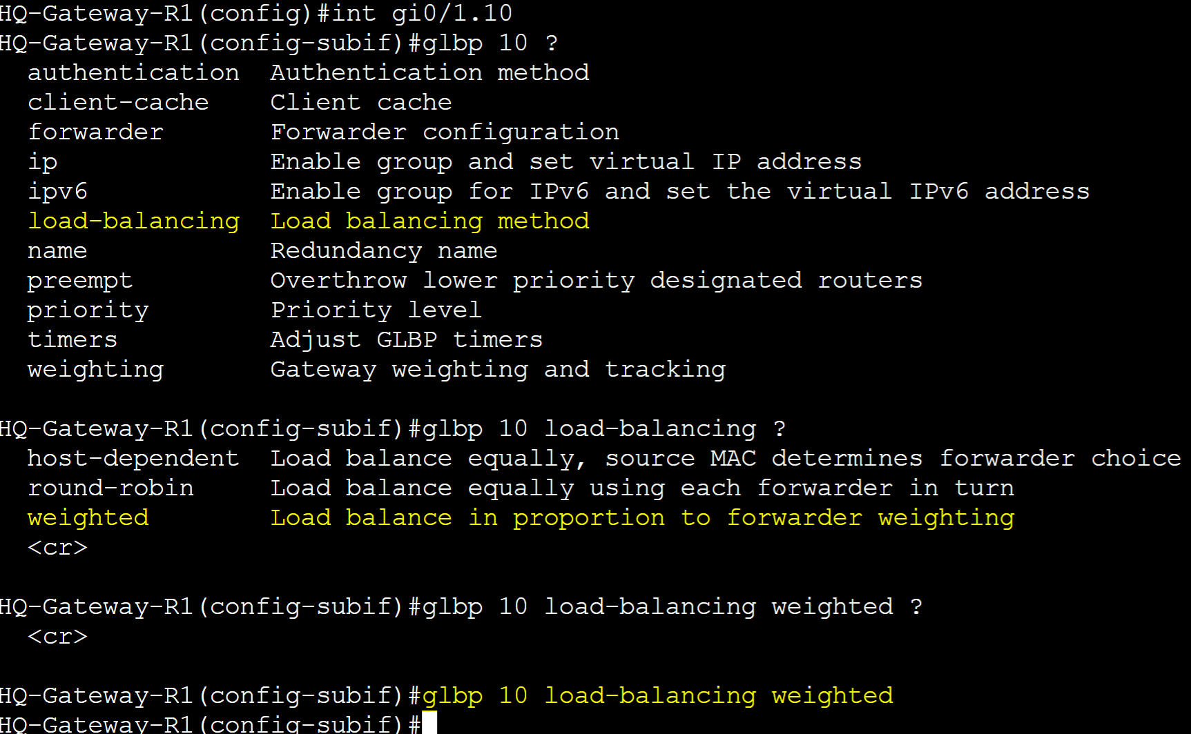
Load Balancing Methods
One of the advantages of GLBP is that it offers load balancing across multiple routers serving as the active gateway for clients on the network. GLBP offers three load balancing methods that is used by the AVG when it responds to ARP requests from clients. By default, the AVG in a GLBP group uses the round robin load balancing method. In this lab scenario, let's demonstrate and dive deep into each method and what it has to offer.
Load Balancing Methods:
Round-Robin Load Balancing
In a Round-Robin deployment, AVFs are used in a fixed sequential order guaranteeing the same load amongst all routers in a group. For example, if there are four AVFs in a group, each client on the network that sends an ARP request for the vIP's virtual MAC address would be assigned virtual MAC 1, followed by virtual MAC 2, then 3, then 4. This method is ideal for situations in which you want to distribute traffic evenly across all available AVFs without taking into account other factors like load or CPU utilization. In this lab scenario, Round-Robin load balancing will be demonstrated for groups 10 and 20. The active AVG for groups 10 and 20 is Gateway-R1.
GLBP Client Cache
The GLBP Client Cache refers to the mapping database that maintains the relationship between client IP address and the corresponding AVF assignment from the AVG. By default, the client cache is not enabled to view but is recommended to enable it on AVG routers to give administrators the ability to view the cached entries of the client to AVF mappings.
Enable Client Cache on active AVG R1 for groups 10 and 20. You can specify the max amount of clients to cache including a cache timeout timer.

Round-Robin Client to AVF Assignment
Group 10 - client 1

Group 10 - client 2
Group 20 - client 1
Group 20 - client 2

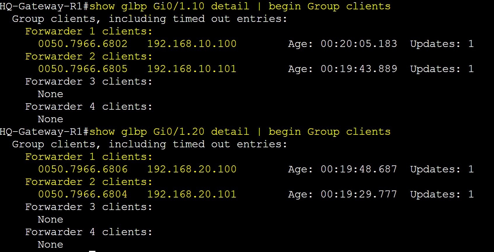
AVG Client-Cache Table
Overview of the client counter statistics per AVF.

Overview of the client detail statistics per AVF.

Alternative overview of the client detail statistics per AVF using the 'show glbp detail' command.
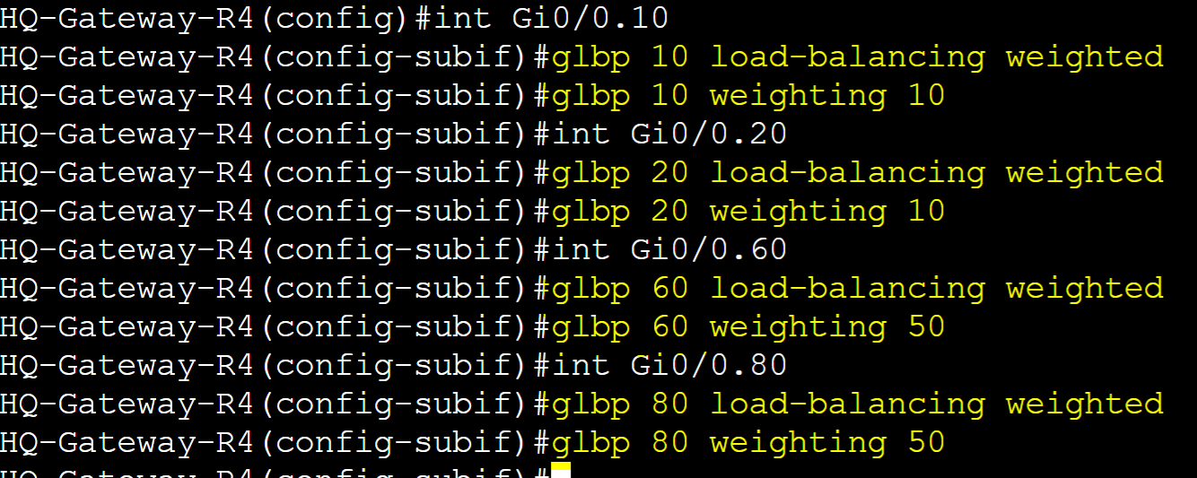
Weighted Load Balancing
In a Weighted load balancing deployment, AVFs are chosen proportionally according to a weight value. With this method, you can assign weights to each AVF router. AVFs with higher weights will be selected more frequently than those with lower weights. This method is ideal for situations where you have a group of AVF routers with different capacities such as CPU power or bandwidth allowing you to assign higher weights to more suitable reliable routers, making them handle more client traffic. In this lab example, let's demonstrate how Weighted Load Balancing works by assigning values on all four routers. The goal here is for groups 10 and 20, GLBP will distribute the traffic load between R1 and R2 in a 2:1 ratio. As for groups 60 and 80, GLBP will distribute the traffic load between R4 and R3 in a 2:1 ratio. Each router in the group will advertise its weight value allowing the AVG to act on those values to assign clients an AVF. A weight value of 0 disqualifies a router from forwarding traffic as an AVF. In the Object Tracking section, the lower and upper weighting parameters in the weighting command will be discussed in detail.
Weight Assignments:
- Group 10/20
- Gateway-R1: 50% (Active AVG)
- Gateway-R2: 25% (Standby AVG)
- Gateway-R3: 15%
- Gateway-R4: 10%
- Group 60/80
- Gateway-R1: 10%
- Gateway-R2: 15%
- Gateway-R3: 25% (Standby AVG)
- Gateway-R4: 50% (Active AVG)
Gateway-R1
Enable Weighted Load Balancing on R1.
Assign weight values to each group on R1.

Verify Load Balancing method and weight value of each GLBP group for R1.

Gateway-R2

Gateway-R3

Gateway-R4
Weighted Client to AVF Assignment
Group 10 - clients


Group 20 - clients

AVG Client-Cache Table
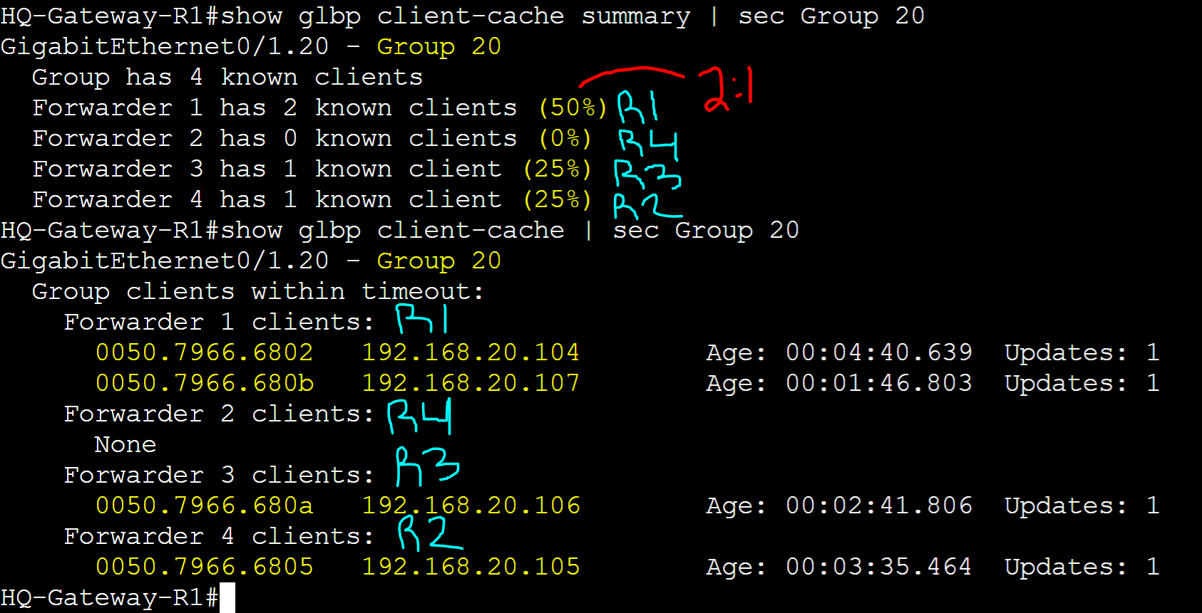
Group 10 Overview of the client counter statistics per AVF.

Group 20 Overview of the client counter statistics per AVF.
Host-Dependent Load Balancing
In a Host-Dependent load balancing deployment, AVFs are used in a predetermined fashion based on client source MAC address which guarantees that the same client will always use the same AVF when it sends subsequent ARP requests for the same vIP. This method is ideal when you want to ensure traffic from a particular client always goes through the same AVF helping maintain session persistence, stateful NAT, or predictable behavior. In this lab example, let's demonstrate how Host-Dependent Load Balancing works by assigning group 20 for all routers the Host-Dependent Load Balancing method.
Client to AVF Assignments:
- Group 20 Clients
- FIN-1: MAC '00.50.79.66.68.02'
- FIN-2: MAC '00.50.79.66.68.05'
- FIN-3: MAC '00.50.79.66.68.0a'
- FIN-4: MAC '00.50.79.66.68.0b'
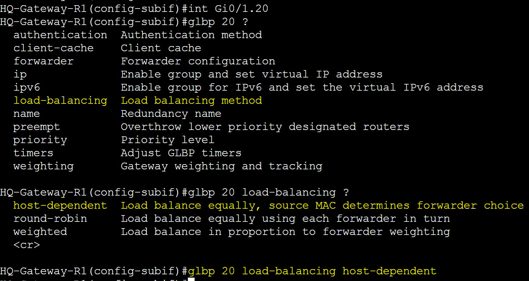
Gateway-R1
Configure Host-Dependent Load Balancing for group 20.
Gateway-R2
Configure Host-Dependent Load Balancing for group 20.

Gateway-R3
Configure Host-Dependent Load Balancing for group 20.

Gateway-R4
Configure Host-Dependent Load Balancing for group 20.

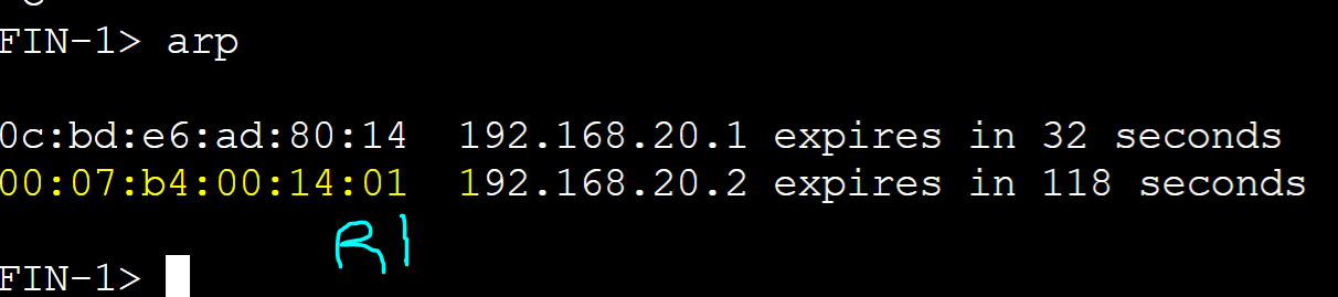
Host-Dependent Client to AVF Assignment
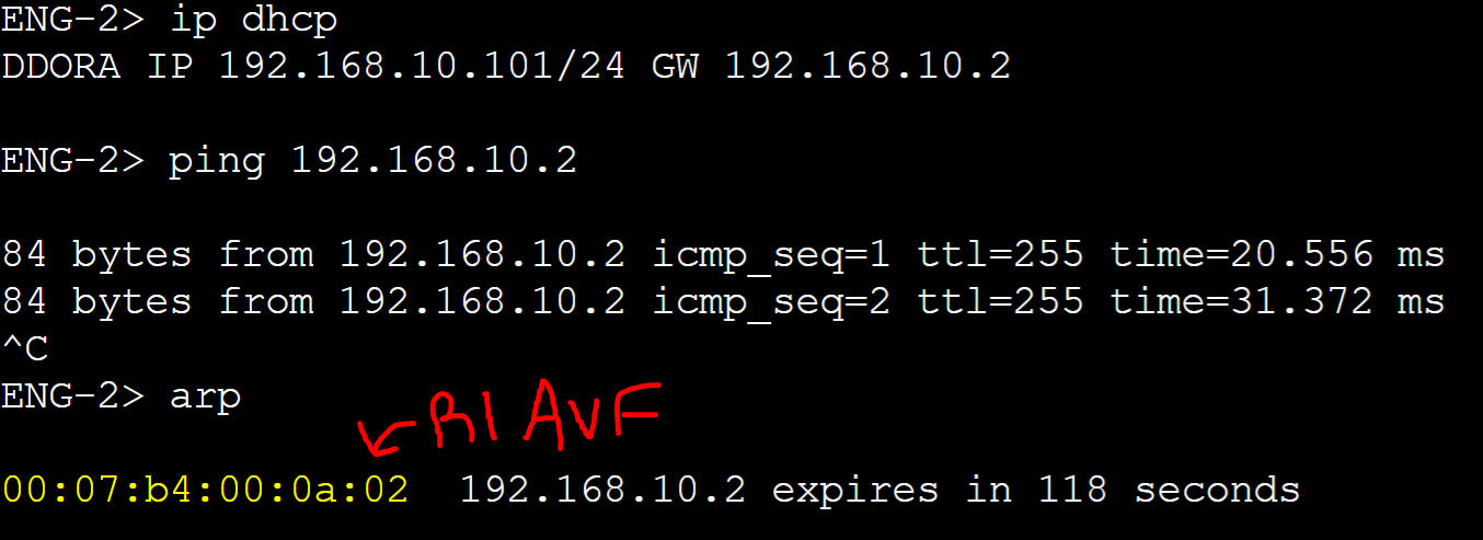
FIN-1 client
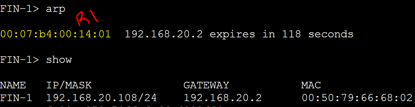
R1 AVG router received an ARP request message from the FIN-1 client with a source address of '0050.7966.6802' and assigned client FIN-1 R1's AVF virtual MAC address.
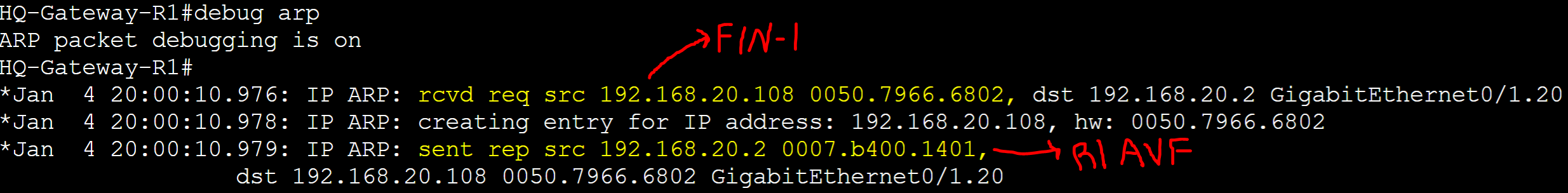
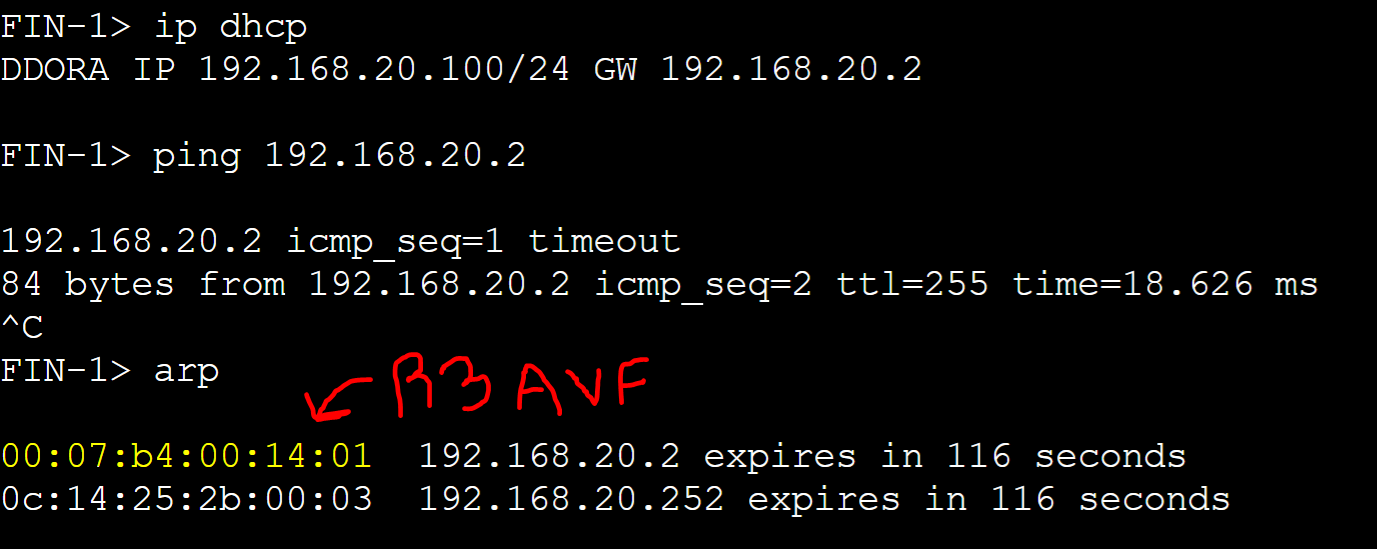
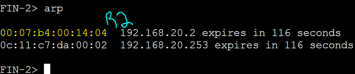
FIN-2 client

R1 AVG router received an ARP request message from the FIN-2 client with source address of '0050.7966.6805' and assigned client FIN-2 R2's AVF virtual MAC address.
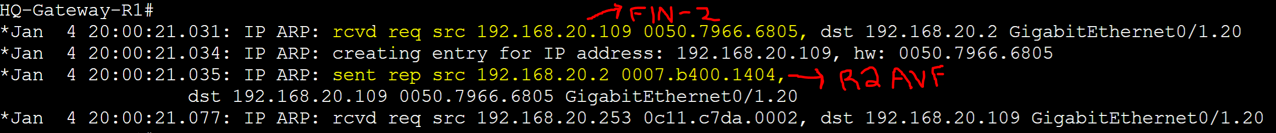
FIN-3 client
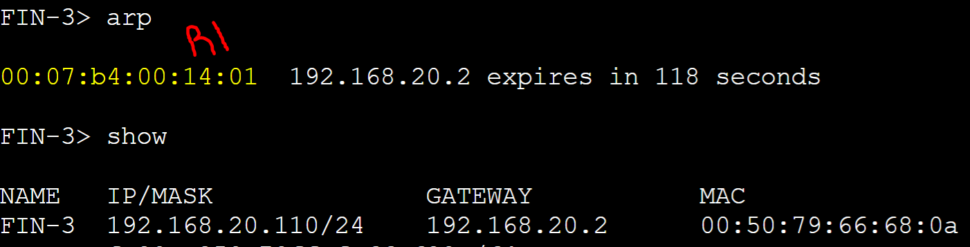
R1 AVG router received an ARP request message from the FIN-3 client with source address of '0050.7966.680a' and assigned client FIN-3 R1's AVF virtual MAC address.

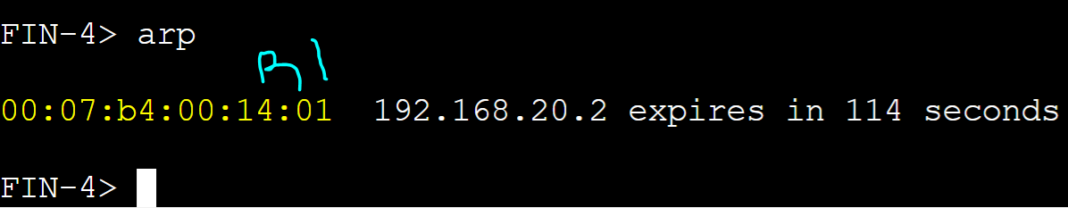
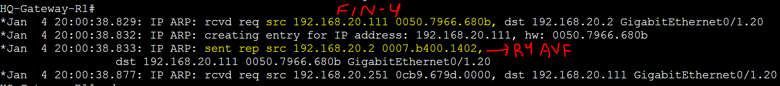
FIN-4 client
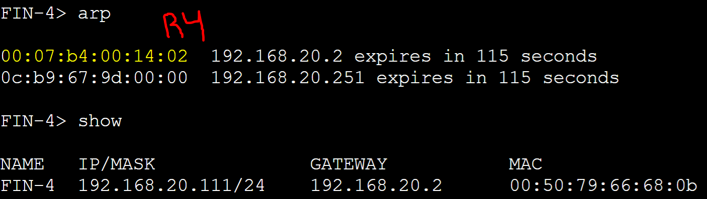
R1 AVG router received an ARP request message from the FIN-4 client with source address of '0050.7966.680b' and assigned client FIN-4 R4's AVF virtual MAC address.
AVG Client-Cache Table
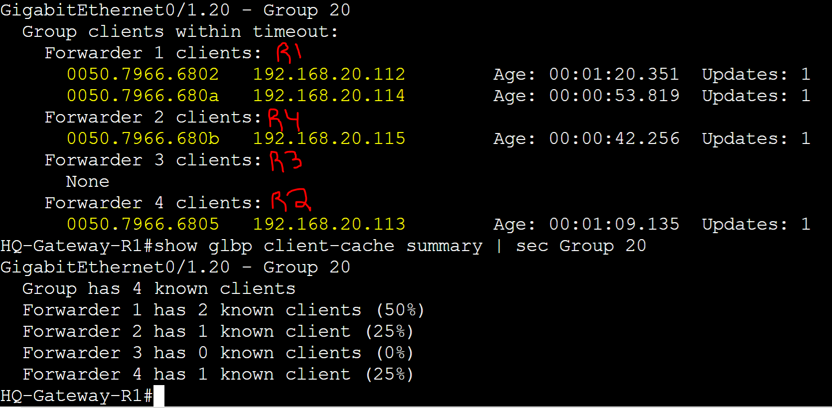
Overview of the client counter statistics per AVF.

Example of the Group 20 clients getting assigned the same AVFs after releasing and renewing their IP address and clearing their ARP tables.
Host-Dependent Load Balancing Summary
To summarize Host-Dependent Load Balancing, group 20 clients will always be assigned the same AVF based on their source MAC address even if the same clients send subsequent ARP requests.
GLBP Timers
GLBP consists of several unique timers that are not present in other FHRP protocols such as HSRP and VRRP. The following AVF failover timers are used by GLBP for ensuring clients can quickly switch to a backup or new AVF in situations where an AVF failure or network topology change occurs. Without these timers, if an AVF fails, the AVG would immediately revoke the MAC address from the GLBP group. Existing hosts will have an invalid MAC entry in their ARP caches and will not be able to properly send packets to the default gateway.
Timer Types:
- Redirect
- Forwarder Timeout
Redirect Timer
The Redirect timer is the interval during which the AVG continues to redirect clients to the old AVF's virtual MAC address. Once the timer expires, the AVG stops responding with the old AVF virtual MAC address in the ARP replies towards new clients. If an AVF fails, GLBP automatically assigns the virtual MAC address to another AVF router in the group, allowing the traffic to continue flowing without interruption. The backup AVF will now use the previously assigned virtual MAC address, effectively taking over the failed AVF's responsibilities.
Forwarder Timeout
The Forwarder Timeout is an interval referring to the time period an active AVG router waits before declaring a failed AVF as inactive if it hasn't received any hello messages from the AVF. This interval also allows the GLBP group to stop responding to incoming packets that consist of the expired virtual MAC address of the failed AVF for hosts that still have the failed AVF vMAC mapped in their ARP cache. The Forwarder timeout timer begins as soon as the Redirect Timer expires. In this lab example, let's demonstrate the Redirect and Forwarder Timeout timers by configuring the timers on Gateway-R1 for GLBP group 20.
Group 20 Timer Assignment:
- Redirect Timer: 60 seconds
- Forwarder Timeout: 14400 seconds (4 hours)
Gateway-R1
Configuring Redirect and Forwarder Timeout timers for GLBP group 20.

Active ARP Table and Client-Cache before AVF failover
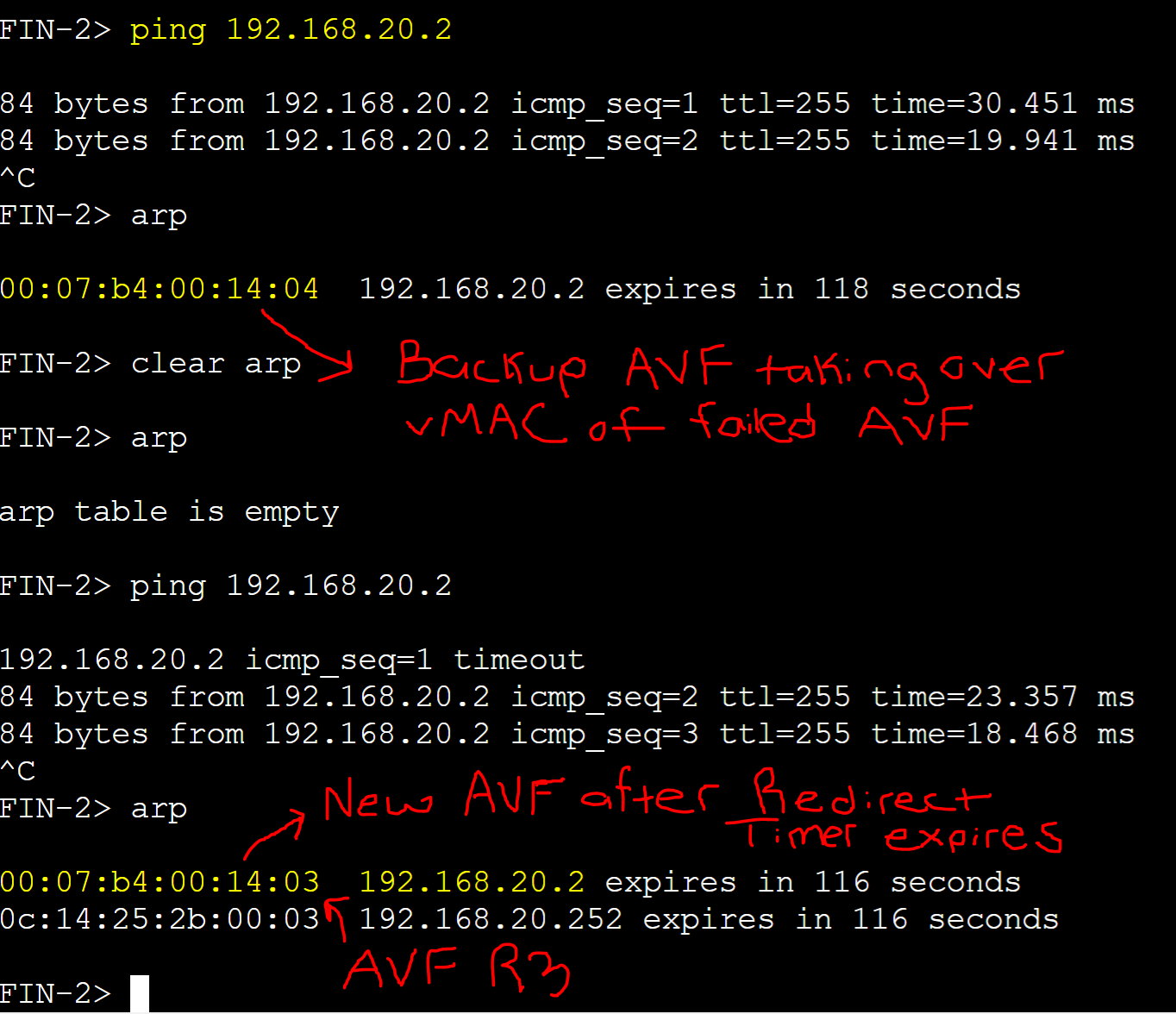
FIN-2 client ARP table.

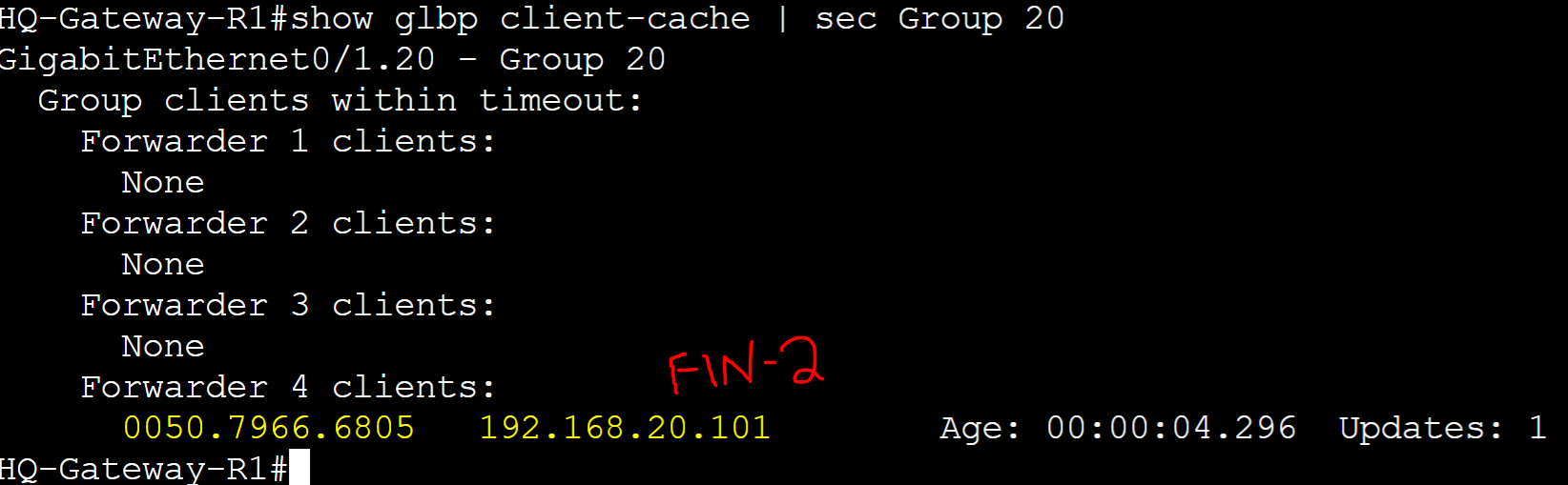
Client-Cache of Gateway-R1.
Testing Redirect Timer for AVF Failover
Shutting down the group 20 interface for AVF Gateway-R2.

FIN-2 client ARP table: Failover AVF assigned.
Updated Client-Cache of Gateway-R1.

GLBP Weighting Track
GLBP Weighting Track is an optional new concept when comparing the rest of the FHRP protocols including HSRP and VRRP. With GLBP, Weighting Track is a feature that refers to the process of dynamically adjusting the weight value assigned to a particular router based on the state of tracked objects in a Object Tracking scenario. The following object tracking scenarios can include Line protocol states of interfaces, IP SLA measurements towards a destination, and even destination IP routes. This GLBP Weighting Track feature allows GLBP to influence the load-balancing behavior by modifying how much traffic is directed toward an AVF gateway in a group. In the Object Tracking section, GLBP Weighting Track will be demonstrated in depth.
Lower and Upper Weight Thresholds
The Lower and Upper weight threshold values is going to be essential to understand when configuring weight decrements via Object Tracking in the next section. These threshold values are used to manage how the weight of a router changes in response to Object Tracking scenarios.
Lower Threshold
- The Lower threshold value defines the minimum weight a router can have to become an AVF for a group
- If a router falls below the lower threshold, it will lose its AVF status
- If the weight of a router has not been dynamically changed, weight values between the lower and upper thresholds are acceptable for AVF roles
- In this example, if the weight value of R1 falls below the lower limit of 10, then the router will lose its AVF role
Upper Threshold
- The Upper threshold value defines the weight a router would need to increase by to regain its AVF role after plummeting below the lower threshold
- In this example, if R1's weight falls below the lower threshold of 10, it will lose its AVF status. To regain its AVF status, R1's weight value will have to increase equal to or above the upper threshold value
Gateway-R1

Object Tracking
Object Tracking is an advanced FHRP concept that allows a gateway router to adjust its priority based on the status of certain network objects such as interfaces or IP routes. This feature enhances the failover mechanism by dynamically adjusting which router is the active gateway in response to changes in the network's state. A tracked object can include things such as interface Line Protocol state, a Tracked IP Route, or a Tracked IP SLA object. GLBP also introduces a new object tracking feature that is not present in HSRP or VRRP. GLBP Weighting Track is a feature that allows AVFs to dynamically adjust their weight values under certain network conditions when using the Weighting Load Balancing option. In this lab example, I will demonstrate Line Protocol and IP SLA objects with the GLBP Weighting Track feature to better understand how Object Tracking works with GLBP.
Line Protocol & IPSLA Object Tracking Lab Topology
Scenario: It is possible for either the IPsec tunnel interface, WAN physical interface, or the individual remote networks in the routing table via the tunnel interface of R1 or R4 to go down due to either an IPsec tunnel misconfiguration or a physical connection issue on the WAN interface. This scenario can thus cause a loss of connectivity out to the Remote Branch site networks or out to the Internet. If this occurs, with Line Protocol and IP-SLA object tracking used simultaneously, we can configure R1 or R4 to dynamically lower their weight values using several weighting track objects. In this scenario, the weight values will only dynamically change to their lower weighting thresholds if either the tunnel interface, or the physical WAN interface goes offline. If only one remote network via the tunnel interface becomes unreachable, the router will still be considered an AVF but with a significantly lower weight value. It is only when both remote networks become unreachable, R1 will disqualify itself as an AVF for all groups. In either scenario, since both routers R1 and R4 are located at the WAN edge of the network, we will disqualify either from becoming an AVF for clients on the network during the time the track objects are down to allow re-routing current traffic to the next available and reachable Internet circuit.
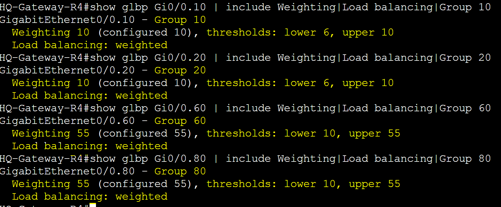
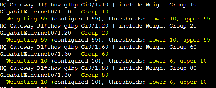
Current AVF Weighting Thresholds
- Gateway-R1 (Groups 10/20)
- Lower: 10
- Upper: 55
- Gateway-R1 (Groups 60/80)
- Lower: 6
- Upper: 10
- Gateway-R4 (Groups 10/20)
- Lower: 6
- Upper: 10
- Gateway-R4 (Groups 60/80)
- Lower: 10
- Upper: 55
Current AVF Load Balancing Weights
- Groups 10/20
- R1: 55%
- R4: 10%
- Groups 60/80
- R1: 10%
- R4: 55%
Router Roles
- Groups 10/20
- Active AVG - R1 / Priority 255
- Standby AVG - R2 / Priority 150
- Groups 60/80
- Active AVG - R4 / Priority 255
- Standby AVG - R3 / Priority 150

Gateway-R1
Displaying R1 weight values for normal operations. R1 has a higher probability of being an AVF for groups 10 and 20 due to a higher weight value.

Gateway-R4
Displaying R4 weight values for normal operations. R4 has a higher probability of being an AVF for groups 60 and 80 due to a higher weight value.
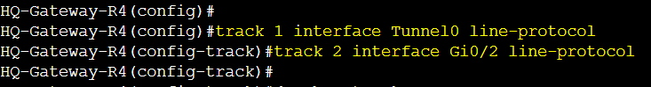
Line Protocol Track Objects
Create two track objects on R1 and R4 in global configuration mode and specify the tunnel interface for one object, and the physical WAN interface for the second object. Once created we will assign both tracked objects to all GLBP groups. Tunnel0 is the overlay tunnel interface towards the Remote Branch site networks off of R1 and R4 and interfaces Gi0/0 or Gi0/2 being the physical WAN interfaces to get out to the Internet.

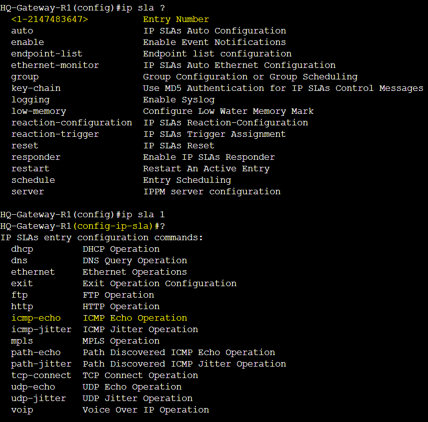
IP-SLA Entries
Create two IP SLA entries on R1 and R4 in global configuration mode and specify the remote networks to ping their reachability status in a separate IP SLA entry. Network '5.5.5.5' for one entry, and network '6.6.6.6' for the second entry. Associate the source interface Tunnel0 for both entries. Once created and scheduled, we will assign each IP SLA entry to a separate track object. Both remote networks reside at the Remote Branch site through the IPsec tunnels of both R1 and R4.
IP SLA Entry Configuration Mode.
Specify the remote networks to measure ICMP reachability from source interface Tunnel0 with a frequency to check every 5 seconds.


Schedule the IP SLA entries to start immediately.


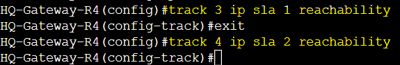
IP-SLA Track Objects
Create two track objects on R1 and R4 in global configuration mode and specify the first IP SLA entry for one object, and the second IP SLA entry for the second object. Associate the reachability attribute on both objects to track. Once created we will assign both tracked objects to all GLBP groups.

Weighting Track Objects
Specify each track object in a weighting track statement on R1 and R4 and configure the weighted decrement value for each track object if it were to go down. In turn, if the Line Protocol states of either the Tunnel or WAN physical interface go down, or both IP SLA remote networks via the Tunnel interface become unreachable, the weight value of the router will decrement below the lower threshold value disqualifying the GLBP AVF role on the router.
Current weight values under normal circumstances.

Configuring the weight tracking statements on R1 and R4.


Verification before R1 Failover
Verifying the routing table of R1 and the static route entries for the remote networks located at the Remote Branch via the tunnel interface through the Internet-1 circuit. Verifying network reachability via ping and traceroute.
Line Protocol 'up' status of the physical WAN interface and Tunnel interface.

Routing table of R1 with the static route entries to the remote networks located at the Remote branch via the tunnel interface.

Remote networks reachable via ping and traceroute via the source Tunnel interface.

R1 Testing Failover
In this example, the FIN-1 client was assigned R2 as its active AVF. AVF R2 has an OSPF redistributed default route to the Internet via R1 using the Internet-1 circuit in addition to having redistributed OSPF routes to the individual remote branch networks. In this topology, both Internet circuits are being used by clients on the network. What determines the circuit being used is based on the least OSPF cost metric towards the default gateway of each router. R1 and R2 utilize the Internet-1 circuit via R1. R3 and R4 utilize the Internet-2 circuit via R4. The AVF assignment on each client determines which Internet circuit the client will use. In this scenario, FIN-1 client will use the Internet-1 circuit via R1.
Scenario 1: R1 Tunnel or Physical Interface failure
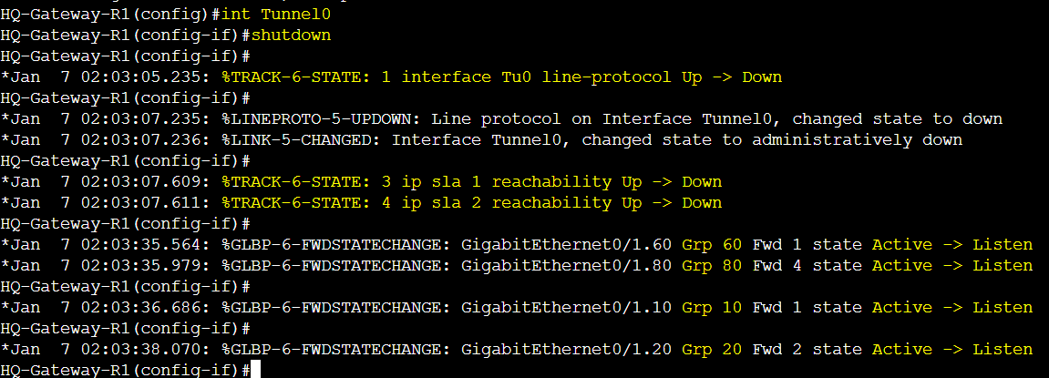
In this example, we will demonstrate the R1 tunnel interface going down but the same results would occur if the physical WAN interface Gi0/0 were to go down instead. I've shutdown R1's tunnel interface to cause the (Track 1 - Line Protocol object for Tunnel0) and (Track 3 & 4 - IP SLA object for networks '5.5.5.5' and '6.6.6.6') to go down. The tunnel between the remote branch router and R1 went down in addition to R1 losing the routing entries to the remote networks of '5.5.5.5' and '6.6.6.6'. This causes R1 to dynamically decrement the weight value for all of its GLBP groups below their lower weight thresholds disqualifying itself from being an AVF for any group.
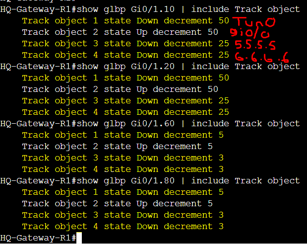
R1 Track objects 1,3, and 4 going down causing the weights to decrement dynamically.
Verification of the R1 weight values dropping below the lower threshold. Router R1 lost its AVF status and can only regain it back once the weight is increased to above or equal to the upper threshold weight value configured.

Verification of R1 losing the active AVF status for its own virtual MAC address of its active groups. Virtual MAC address of R1 handed off to other AVF routers during failover.

Verification of the track objects 1,3, and 4 in the 'Down' status.
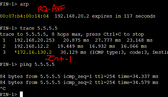
FIN-1 client failing over to the tunnel via R4 to reach the Remote branch networks '5.5.5.5' and '6.6.6.6' through the Internet-2 circuit.
Re-enabled R1's tunnel interface to have R1 recover. Track objects changed to state 'up' allowing R1 to regain its AVF role for its active groups.

Verification of the weight values returning to their configured state. Router R1 can only regain its AVF status back if the weight is equal to or above the upper threshold weight value. R1 has met this condition.

Verification of R1 being an active AVF for its virtual MAC address.

Verification of FIN-1 client taking the Internet-1 circuit for any traffic destined to the Remote Branch as R1 is the preferred gateway for routers R1 and R2 in the topology. Client FIN-1 has been assigned R2 as its AVF. R2 has a least OPSF cost to R1 to get out to the remote networks including the default route out to the Internet.

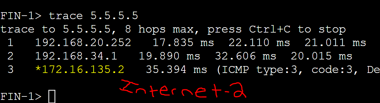
Scenario 2: Unreachable Remote Branch Network
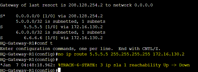
In this example, we will demonstrate a tracked IP SLA object for a remote network becoming unreachable. This scenario can be caused by a misconfiguration or a missing network in the routing table between routers. In this lab example, I will remove the '5.5.5.5' remote network from R1's routing table causing the IP SLA track 3 object to go down. With how I have the weighted track statements configured, if only one network through the tunnel interface becomes unreachable, R1 will still be considered an AVF but with a lower weight value becoming less preferred to become an AVF for clients on the network. This can be beneficial for new clients to be assigned to higher weighted routers to take the most efficient path through R4.
Removing the Remote branch network from R1's routing table causing the track object 3 to go down.
Verification of R1's weight values dropping but still within the AVF range. The goal here is to drop the weight low enough to reduce the number of new clients being assigned to R1 as their AVF. With the goal of reducing the impact to clients on the network, this allows administrators to troubleshoot the tunnel between routers R1 and the Remote branch gateway to determine the cause and remediate the issue as quickly as possible. If a second remote network becomes unreachable, Router R1will completely lose its AVF status and can only regain it back once the weight is increased to above or equal to the upper threshold weight value configured.

Verification of R1 retaining its AVF status for its own virtual MAC address of all its active groups.

Verification of the track object 3 in the 'Down' status.

FIN-1 client is still able to reach remote network '6.6.6.6' off of R1 as its AVF but unable to reach network '5.5.5.5'.

I've re-added the remote network '5.5.5.5' via the tunnel interface on R1. The track object 3 changes to state 'up' and causes the weight value of R1 to return to its configured state.

Verification of the weight values of R1 returning to their normal configured state.

FIN-1 client is able to reach remote network '5.5.5.5' via the tunnel interface of AVF R1.
