Virtual Router Redundancy Protocol
Sections:
- Lab Topology
- Group Numbers
- Virtual IP and Virtual MAC Address
- VRRPv3 Base Configuration
- Master & Backup Roles
- VRRP States
- Advertisement Packets
- Multicast Address
- Priority
- Pre-emption
- Authentication
- Object Tracking
- Multi-Group Load Sharing
Overview:
- VRRP is a IEEE open standard protocol designed to provide high network availability and redundancy for IP networks
- VRRP is critical in multi-vendor environments to ensure non Cisco devices can utilize FHRP to support high availability for default gateways. Unlike HSRP, VRRP is generally considered to have better scalability and performance in large scale, multi-vendor environments
- VRRP and HSRP share similarities in features and command structure thus the goal of this lesson re-look over the same concepts from HSRP but include the differences between the two FHRP protocols
- Let's dive deep into the concepts of VRRP by configuring Cisco routers in a lab environment
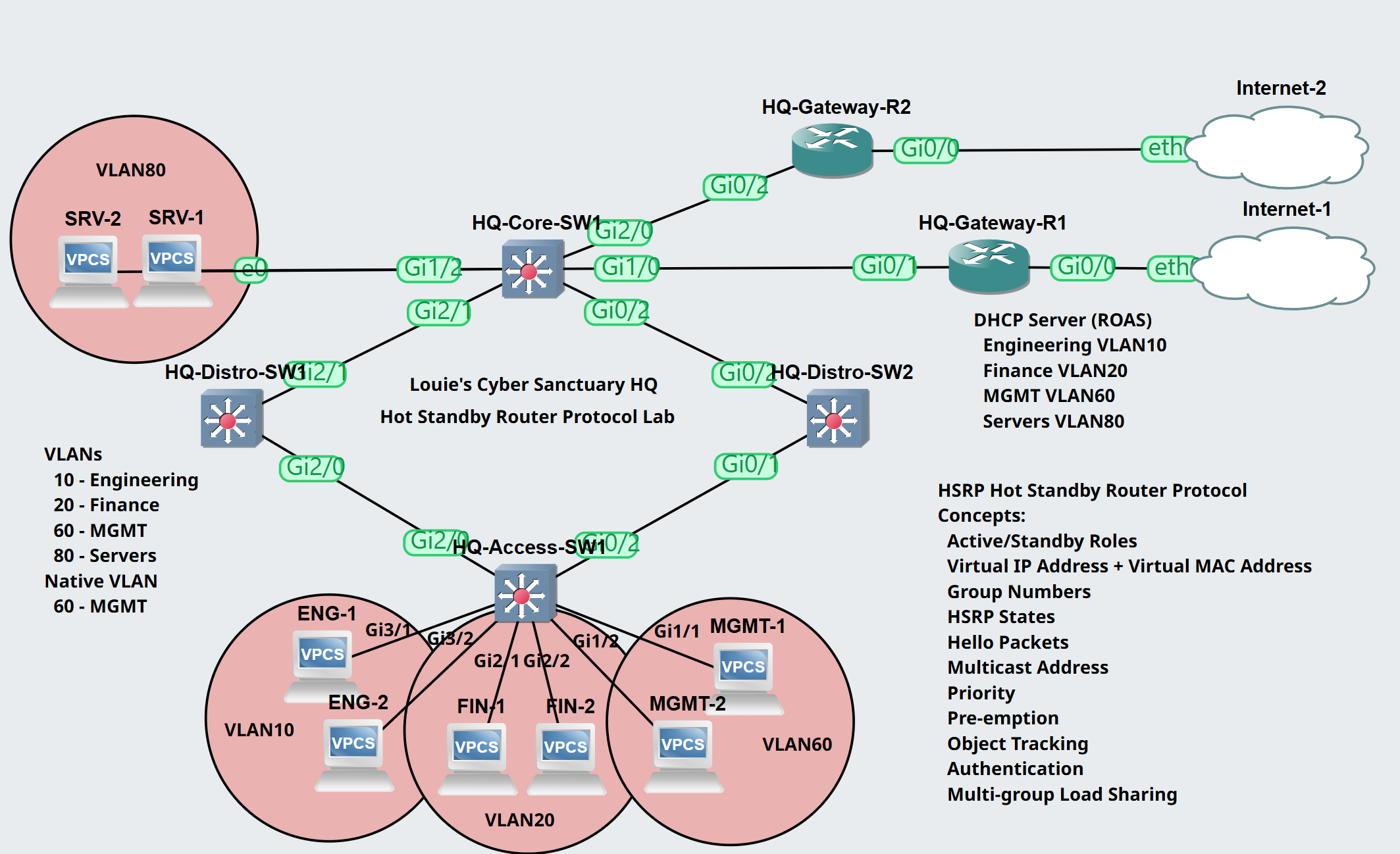
Lab Topology
In this lab scenario, we will configure the concepts of VRRP on Gateway-R1 and Gateway-R2.
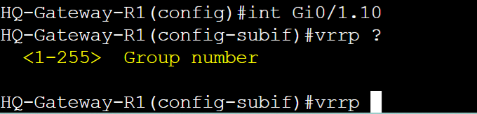
Group Numbers
Group Numbers in VRRP represent the routers that are participating in a VRRP instance. In both VRRPv2 and VRRPv3, you can have up to 255 groups. The interfaces serving as the default gateway for hosts on the network will be assigned a group number. Group numbers have to match between both routers that are part of the same VRRP group within the same VLAN or subnet.
HQ-Gateway-R1
VRRPv2 group numbers.
VRRPv3 group numbers.
Virtual IP and Virtual MAC Address
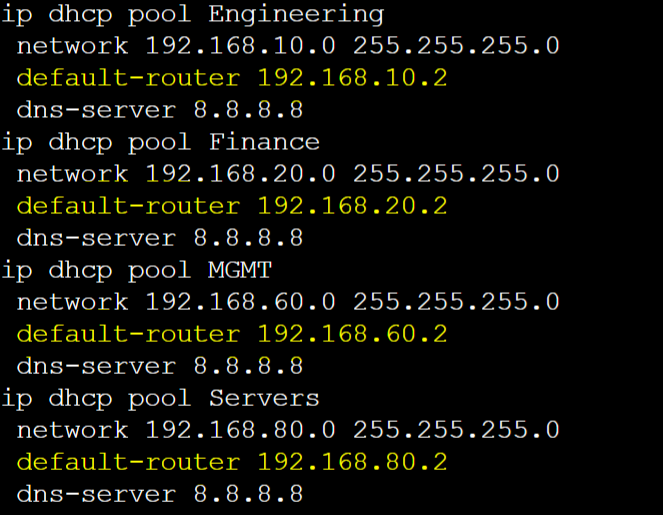
The Virtual IP in VRRP is what logically allows routers in a VRRP group to work together to serve as the default gateway of the network. The VIP address must match between all routers in a group. Unlike HSRP, network clients can either use the defined unique vIP of the group or the physical IP address of either router configured as the vIP. In this lab example, I have set up DHCP scopes on the Core switch serving each VLAN and set the default gateway option to correspond to the appropriate VRRP VIP addresses of each group.
The Virtual MAC address, just like the VIP, must match between all routers in a VRRP group and is automatically configured depending on the VRRP version. All IP addresses need an associated MAC address in IP networking. By default, VRRPv2 is enabled when configuring VRRP for the first time. Both VRRPv2 and v3 use the VMAC format '0000.0c07.acXX' where 'XX' represents the group number in hexadecimal.
HQ-Core-SW DHCP vIP
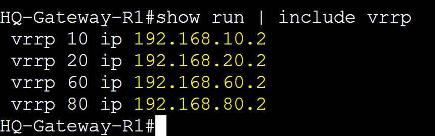
HQ-Gateway-R1 vIP
HQ-Gateway-R2 vIP
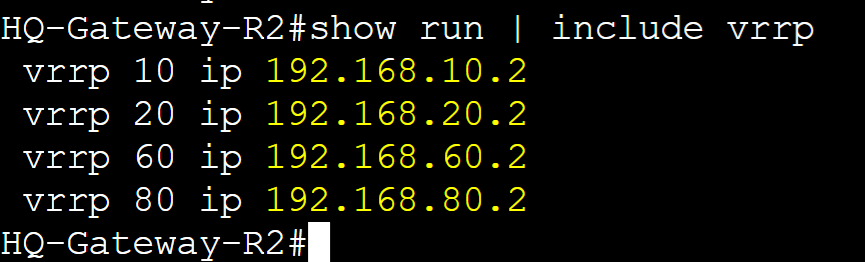
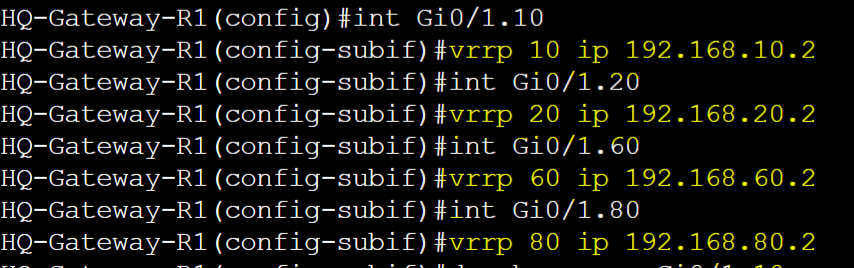
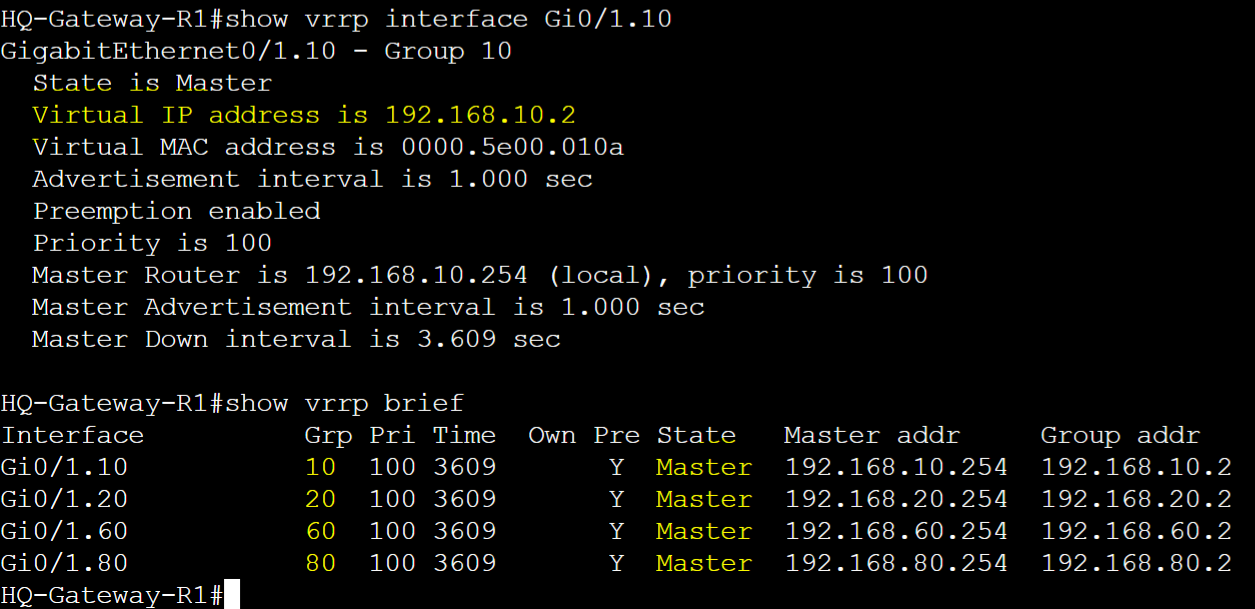
HQ-Gateway-R1 and HQ-Gateway-R2 VRRP Base Configuration
HQ-Gateway-R1
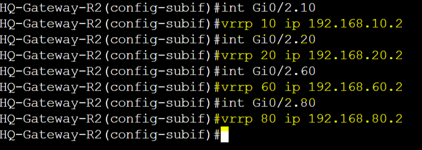
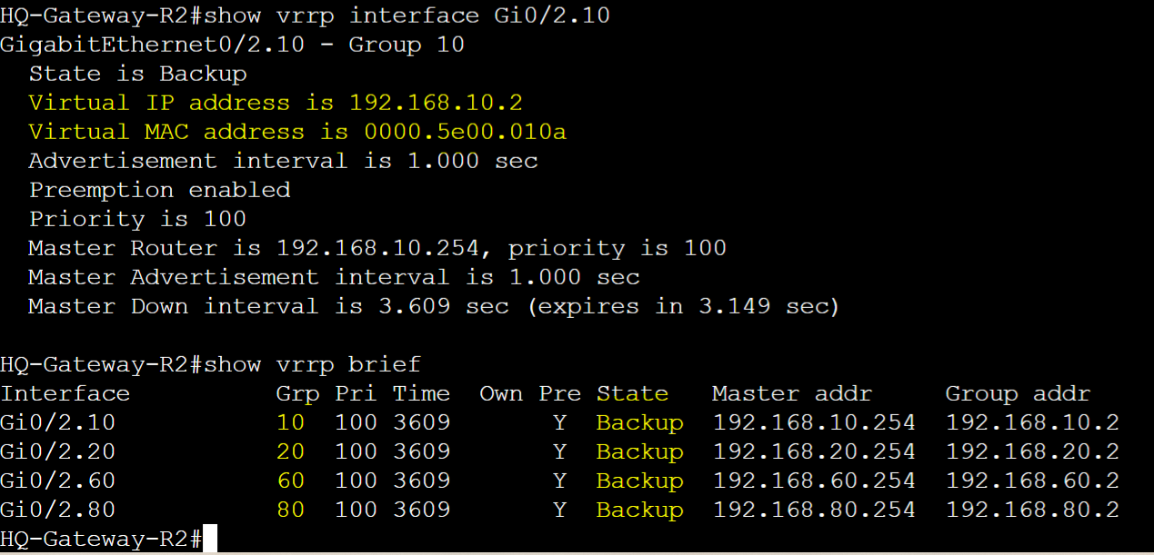
HQ-Gateway-R2
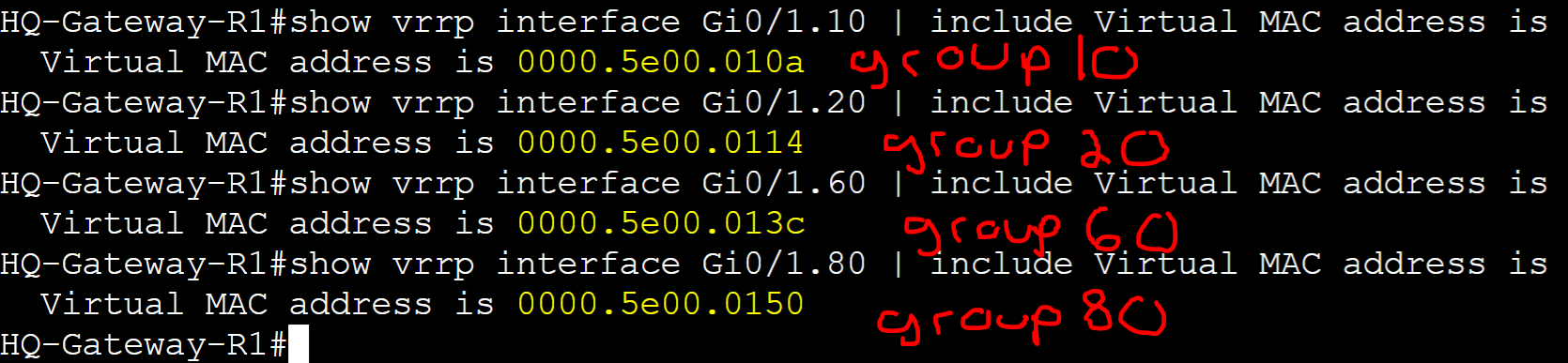
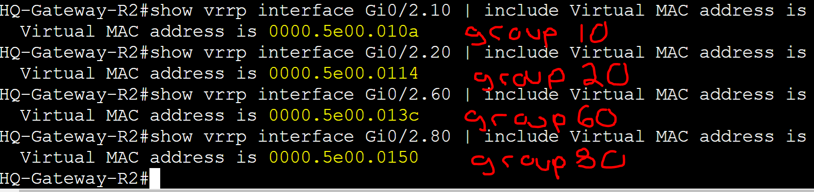
HQ-Gateway-R1 and HQ-Gateway-R2 vMAC per group
HQ-Gateway-R1
HQ-Gateway-R2
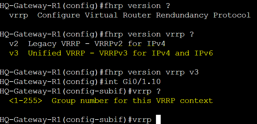
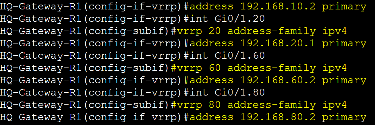
VRRPv3 Base Configuration
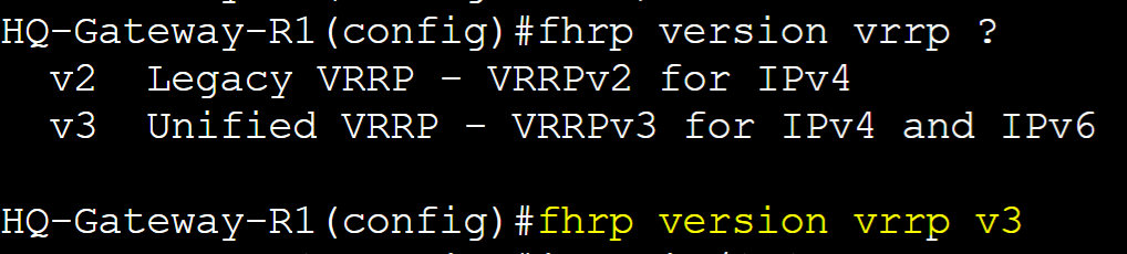
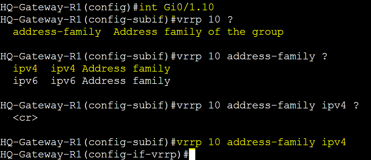
VRRPv3 is an enhanced version of VRRP supporting both IPv4 and IPv6 protocols. VRRPv3 utilizes the address family hierarchy structure when configuring groups. The address family refers to the type of IP address (IPv4 or IPv6) that will be used for the vIP in the VRRP configuration. This is a key concept to ensure VRRP is set up correctly for the type of network you're working with.
VRRPv3 enables dual-stack operation, meaning it can manage both IPv4 and IPv6 vIPs in the same network which provides greater flexibility for network redundancy.
HQ-Gateway-R1
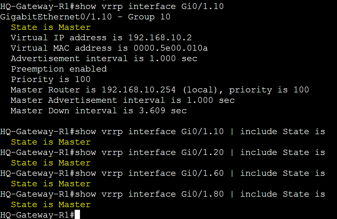
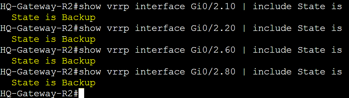
Master and Backup Roles
In VRRP, Master and Backup roles are assigned to routers in a group. One router will serve as the master gateway handling all user traffic while the backup gateway is ready to take over in cases when the master gateway fails. By default the router that is first assigned to a group will assume the master role. We can manipulate router roles with the concept of Priority and Pre-emption discussed later.
HQ-Gateway-R1
HQ-Gateway-R2
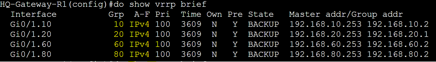
VRRP States
Unlike HSRP, VRRP routers go through a fewer series of states used to determine it's role in the VRRP group. These states in order go from: Initial, followed by either Master or Backup.
VRRP States
- Init State: Router is waiting to start the VRRP process
- Backup State: Backup router waiting to take over master role if primary router fails
- Master State: Primary router actively handling network traffic
HQ-Gateway-R1
Advertisement Packets
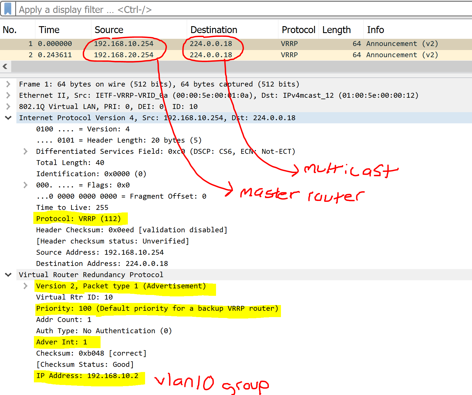
Advertisement Packets are essential in VRRP as only the master routers send these messages to the multicast address of all VRRP routers to advertise the roles during the election process and as keepalives for VRRP master failover. Advertisement packets contain information such as advertisement and hold intervals, priority, version, and group vIP. VRRPv2 and VRRPv3 utilize IP protocol 112 in the encapsulated IP header. Below are some distinctions and similarities between VRRPv2 and VRRPv3 packets.
Similarities
- Uses multicast address 224.0.0.18 (All VRRP routers)
- IP Protocol 112
- Only the Master router sends adv packets
Differences
- VRRPv3 supports IPv6
VRRPv2 Advertisement Packets
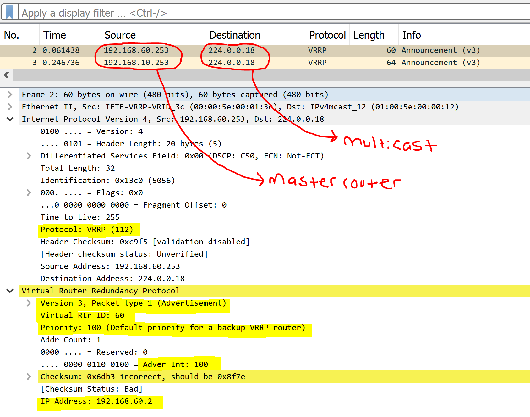
VRRPv3 Advertisement Packets
Multicast Address
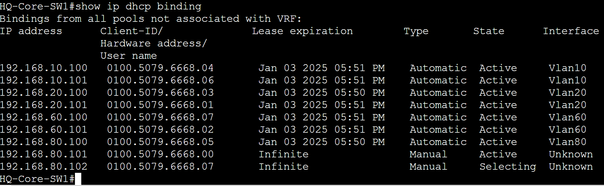
Let's dive more in depth with the vMAC concept by configuring the vIP of each default gateway amongst all clients on the network via DHCP and examining the MAC address of the VRRP group in each VLAN. The vMAC of the VRRP group is using the VRRP format '0000.5e00.01XX' where 'XX' represents the VRRP group number in hexadecimal.
HQ-Core-SW
Client DHCP binding table.
ARP table for VRRP group vMACs.
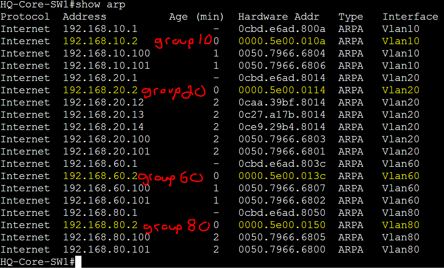
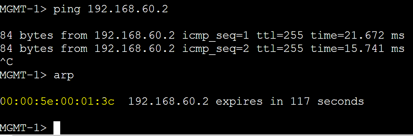
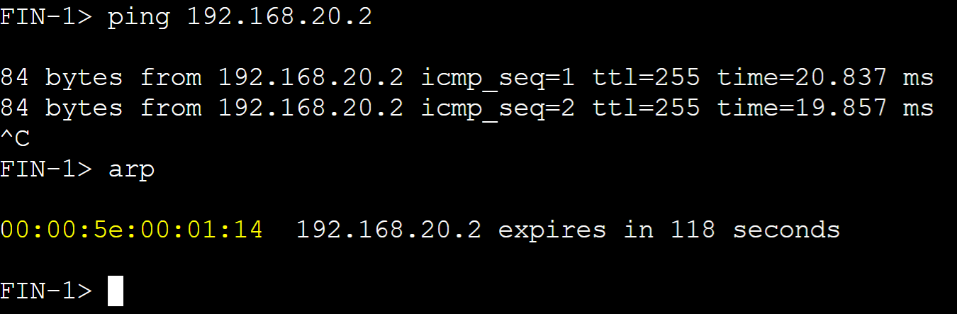
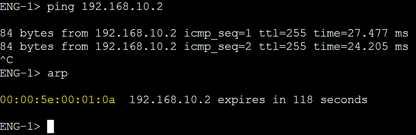
Client ARP Tables
vMAC for vlan60 master router.
vMAC for vlan20 master router.
vMAC for vlan10 master router.
vMAC for vlan80 master router.
Priority
Priority is the value that determines which router in a VRRP group becomes the Master router. The router with the highest priority becomes the Master router. By default all VRRP routers use the priority value of 100 and can be manually set in the range of 0-255. Pre-emption is enabled by default and can be used to allow higher priority routers to retake over the master role after a failure. In this lab example, I will adjust the priority value of Gateway-R2 to a higher value so it becomes the preferred master router and a lower value on Gateway-R1. Without Pre-emption, if Gateway-R2 were to fail, Gateway-R1 will take over and stay as the master router. With Pre-emption, if Gateway-R2 were to come back online after a failure, it would retake the master role as its priority is configured to a higher value than Gateway-R1.
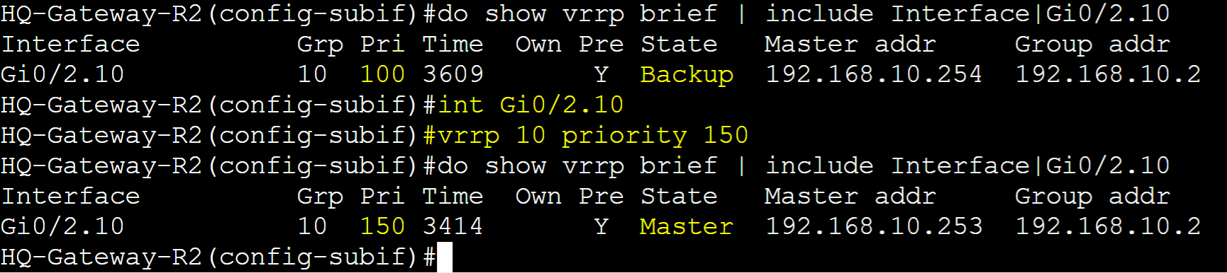
HQ-Gateway-R2
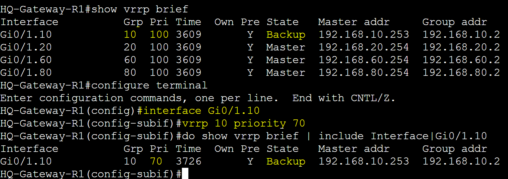
HQ-Gateway-R1
Pre-emption
Pre-emption is used in conjunction with priority values. Pre-emption is a feature that allows a higher priority router to take over the role of the master router in a failover scenario. This feature can be beneficial in situations such as planned maintenance or maintaining optimal network performance by ensuring the most preferred router handles traffic. However it is important to monitor routers in the VRRP group with Pre-emption enabled in cases where the higher priority router continues to go offline then back online causing brief disruptions in the network. As Pre-emption is enabled by default in VRRP, in this lab example, I will cause a failover scenario on Gateway-R2 for VRRP group 10 triggering Gateway-R1 to transition to the master role. Once Gateway-R2 is brought back online, it will retake over as the master role.
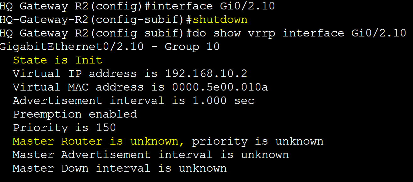
HQ-Gateway-R2
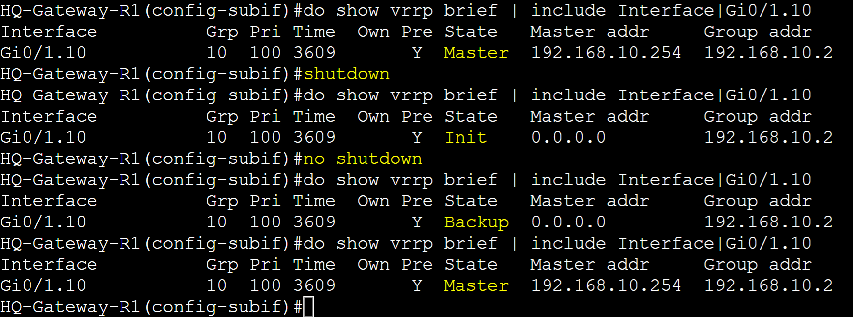
Pre-emption enabled by default for VLAN10 sub-interface in VRRP group 10.
Failure scenario on Gateway-R2.
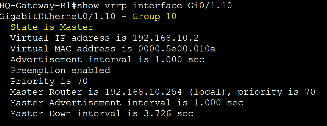
Results of the failover scenario on Gateway-R1 taking over as Master router role.
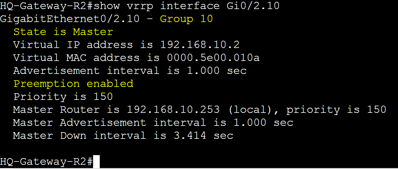
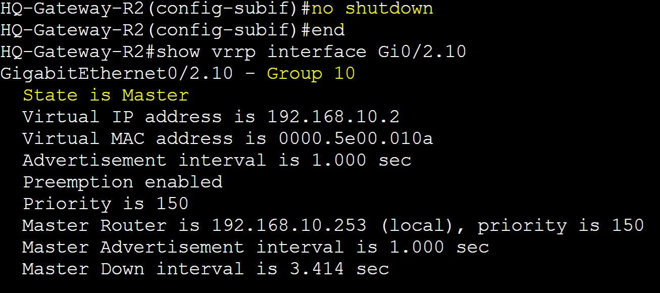
With Pre-emption, Gateway-R2 retaking over as the Master once the group interface is brought back online.
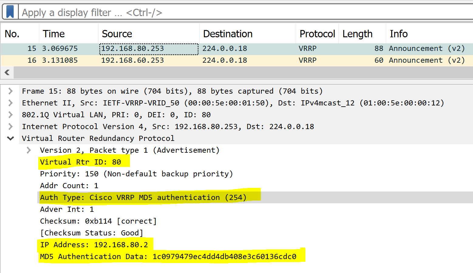
Authentication
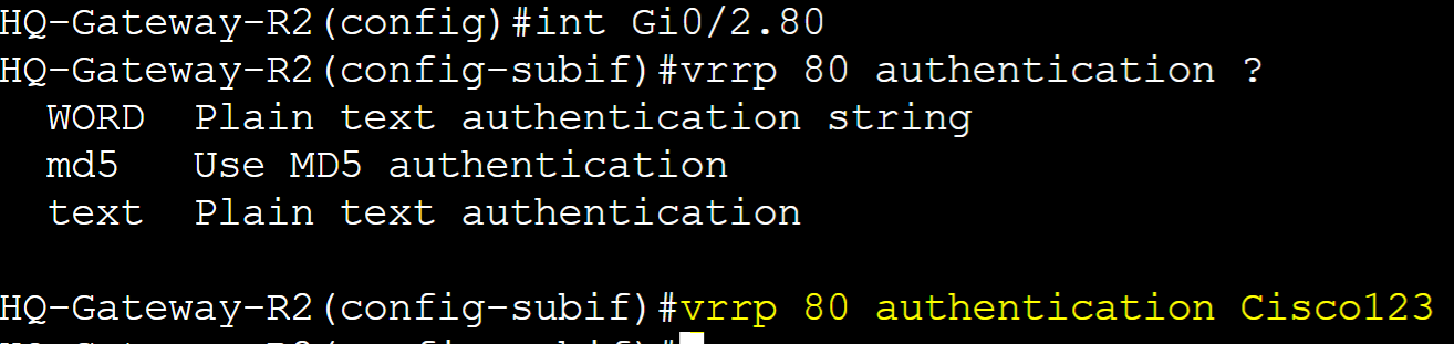
VRRP Authentication is an optional security feature that allows routers in an VRRP group to authenticate each other before participating in the protocol. This feature can prevent unauthorized devices from participating in the VRRP group. VRRP just like HSRP, allows for a select few authentication types including plain text or MD5 authentication. MD5 authentication is a cryptographic hash function that encrypts a plain text password and thus is more secure. In this lab example, I will configure Plain text and MD5 authentication in separate scenarios for the VLAN80 VRRP group and then analyze a packet capture with the authentication information included.
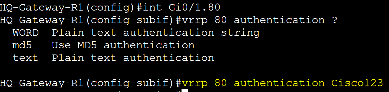
Plain Text Authentication
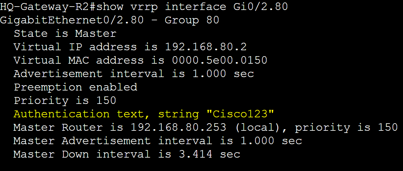
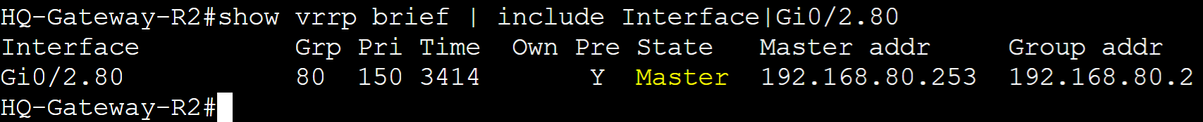
Gateway-R1
Gateway-R2
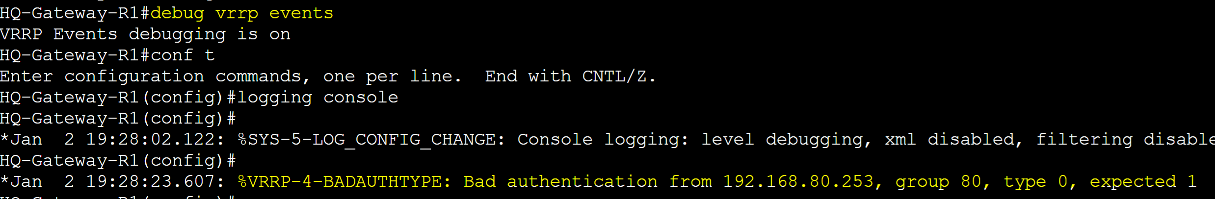
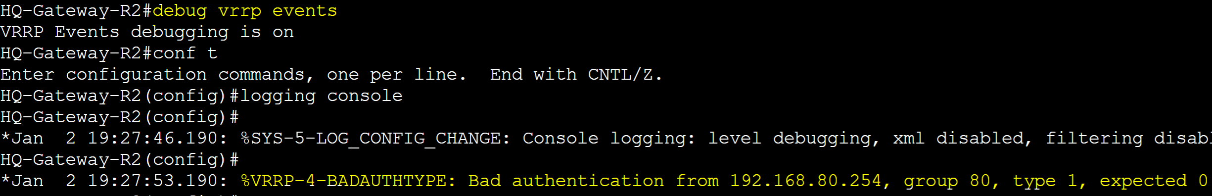
Gateway-R1 & Gateway-R2 Authentication Troubleshooting
In cases where both routers in a VRRP group are showing as Master, you can issue the 'debug vrrp events' command on both routers to determine the cause. In this case, bad authentication is the concern and in this situation, authentication is not configured on Gateway-R2.

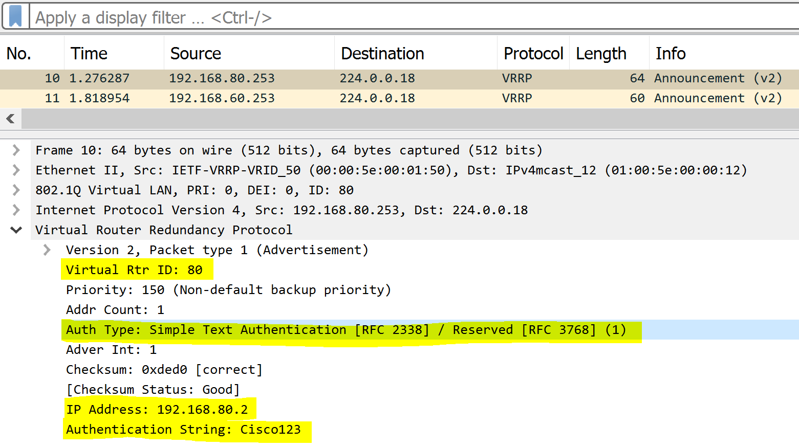
Plain Text Packet Capture
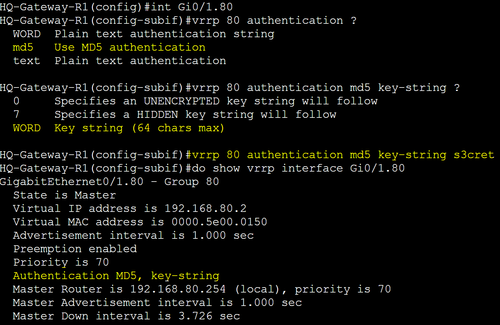
MD5 Authentication
Gateway-R1
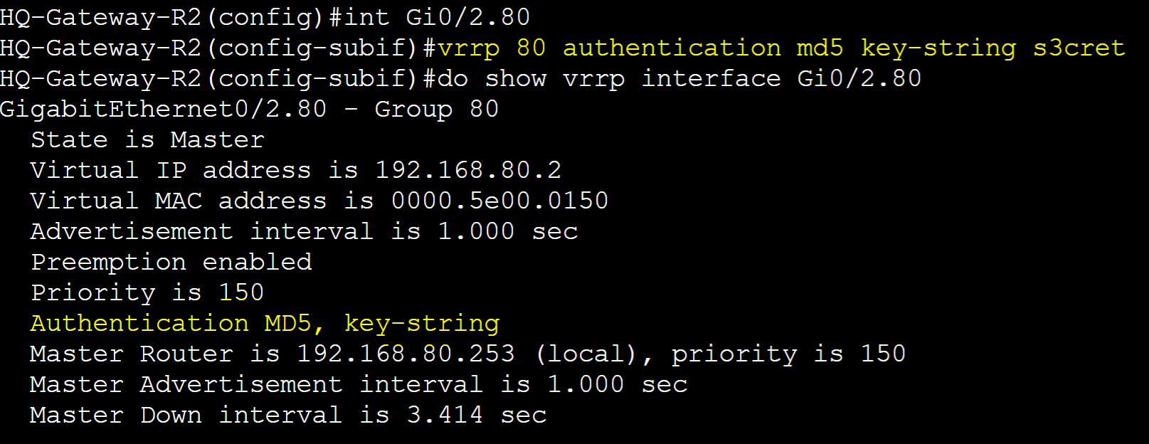
Gateway-R2
MD5 Packet Capture
Object Tracking
Object Tracking is an advanced VRRP concept that allows the VRRP master router to adjust its priority based on the status of certain network objects such as interfaces or IP routes. This feature enhances the failover mechanism by dynamically adjusting which router is the master in response to changes in the network's state. A tracked object can include either an interface Line Protocol state, a tracked IP route, or a tracked IP SLA object. In this lab example, I will demonstrate all three scenarios to better understand how Object Tracking works for VRRP.
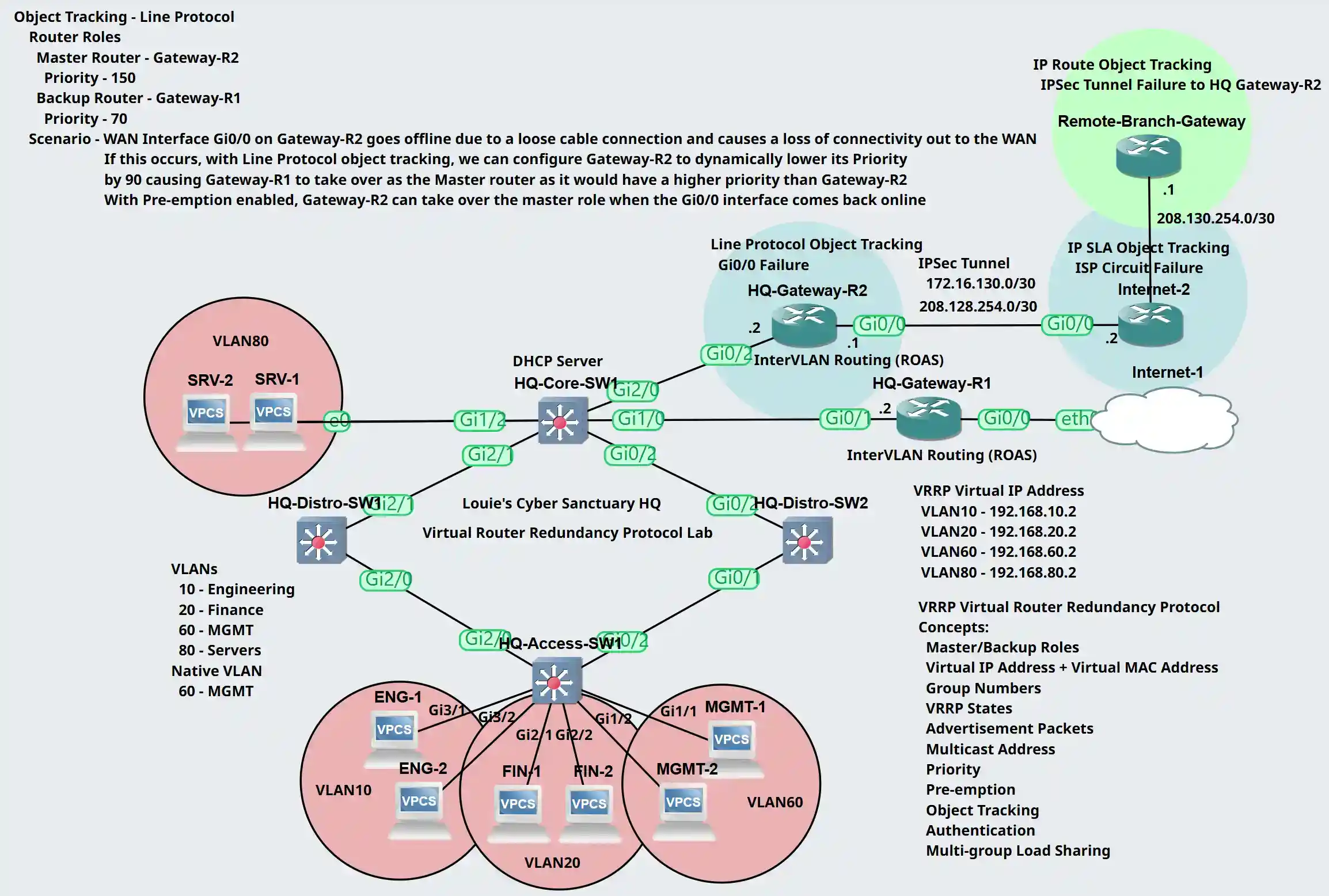
Interface Line Protocol Object Lab Topology
Scenario: Gateway-R2's WAN Interface Gi0/0 goes offline due to a loose connection and causes a loss of connectivity out to the WAN. When this occurs, we will have Gateway-R2 dynamically lower its priority by 90 for all its VRRP groups causing Gateway-R1 to take over as the master router with the higher priority. Pre-emption will be enabled on Gateway-R2 by default so it can retake over as the master router once the Gi0/0 WAN interface of Gateway-R2 comes back online.
Router Roles
- Gateway-R1: Backup role with Priority 70
- Gateway-R2: Master role with Priority 150
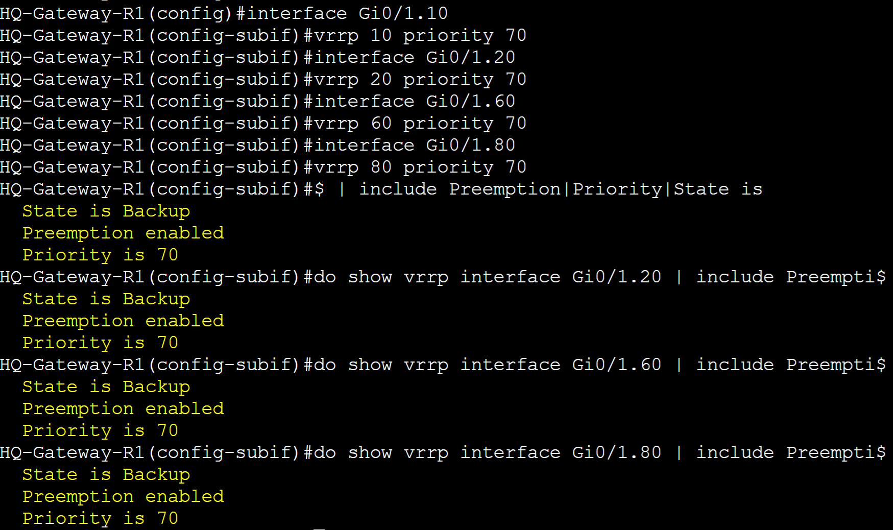
Gateway-R1
Configured Priority 70 to all groups with Preemption enabled by default.
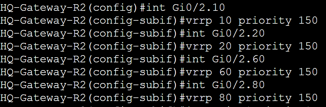
Gateway-R2
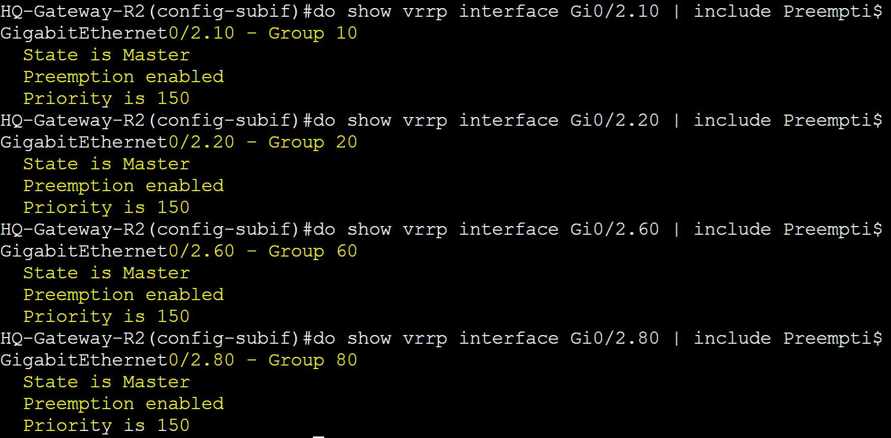
Configured Priority 150 to all groups with Preemption enabled by default.
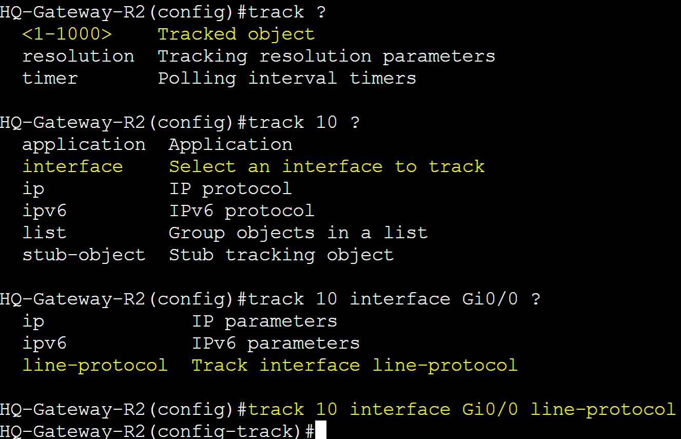
Created a Track object in global configuration and specified the interface and line-protocol attribute to track. Once created we will assign this tracked object to all the VRRP groups. Gi0/0 is the WAN link of Gateway-R2 towards the ISP router.
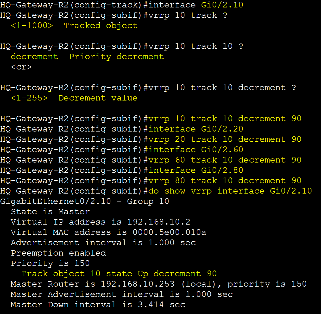
Specified the track object in each VRRP group interface and associated the object with the decrement priority sub commands with the decrement value. In turn, if the line protocol state of interface Gi0/0 goes down, the priority of the VRRP groups will decrement by 90.
Testing Failover
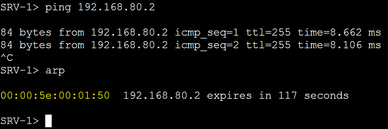
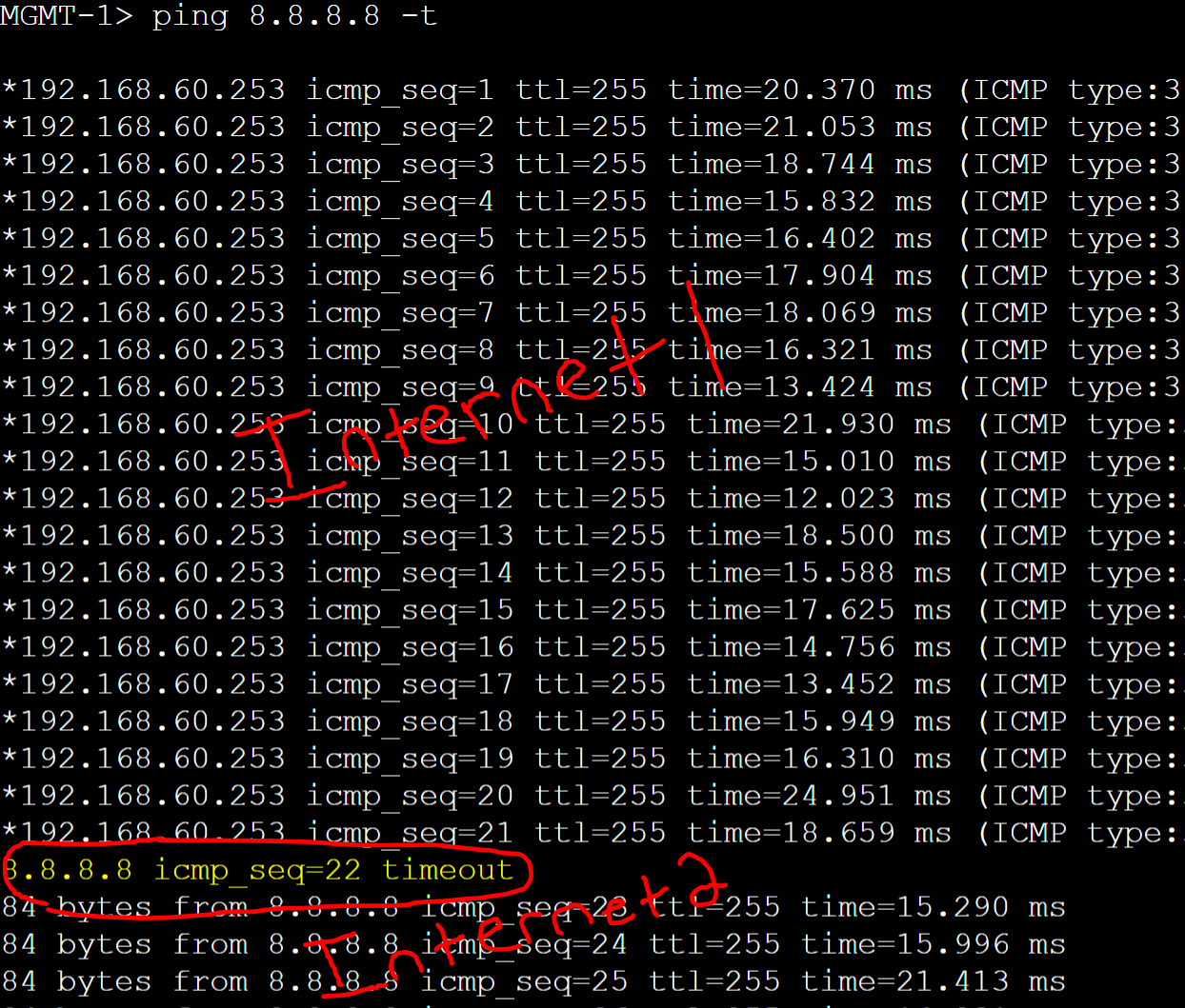
MGMT PC gateway failover to Gateway-R1 based on the single ICMP timeout.
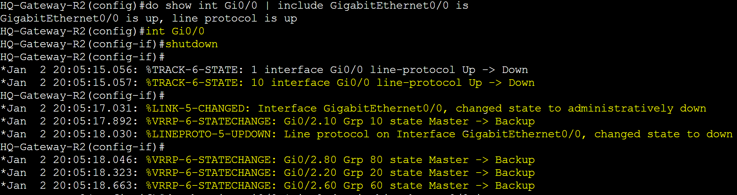
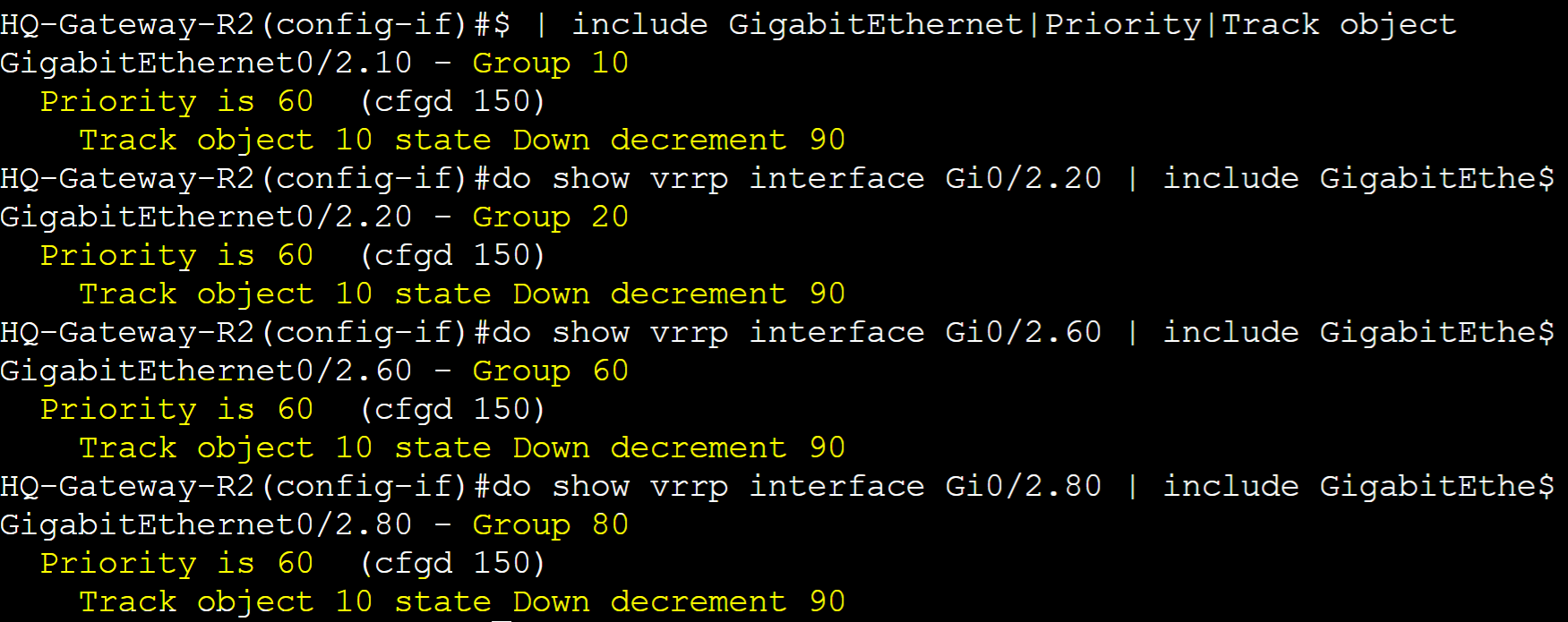
I've shutdown the Gi0/0 interface of Gateway-R2 to cause the track object to take effect. Line protocol of interface Gi0/0 went down causing the VRRP groups to decrement their priority by 90. Groups transitioned to the Backup state and Gateway-R1 took over as the master router.
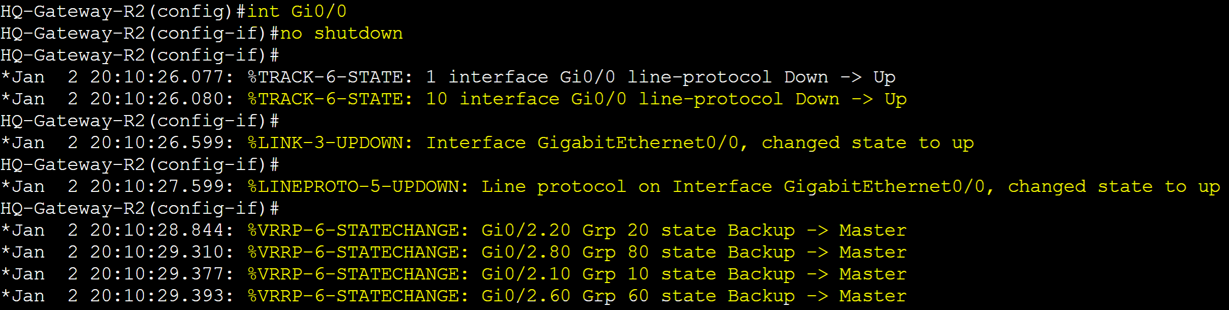
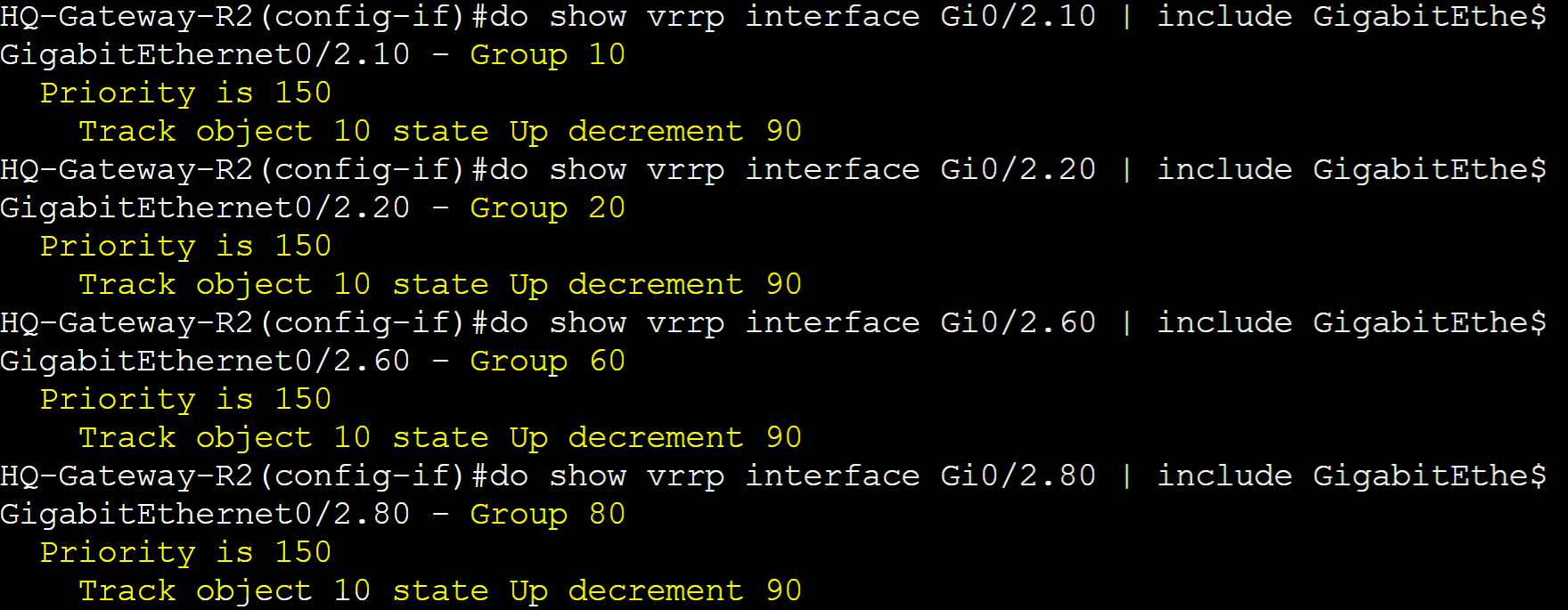
Re-enabled the Gi0/0 interface on Gateway-R2. Line protocol object triggered and with Pre-emption configured, Gateway-R2 re-took over as the master router with the higher priority.
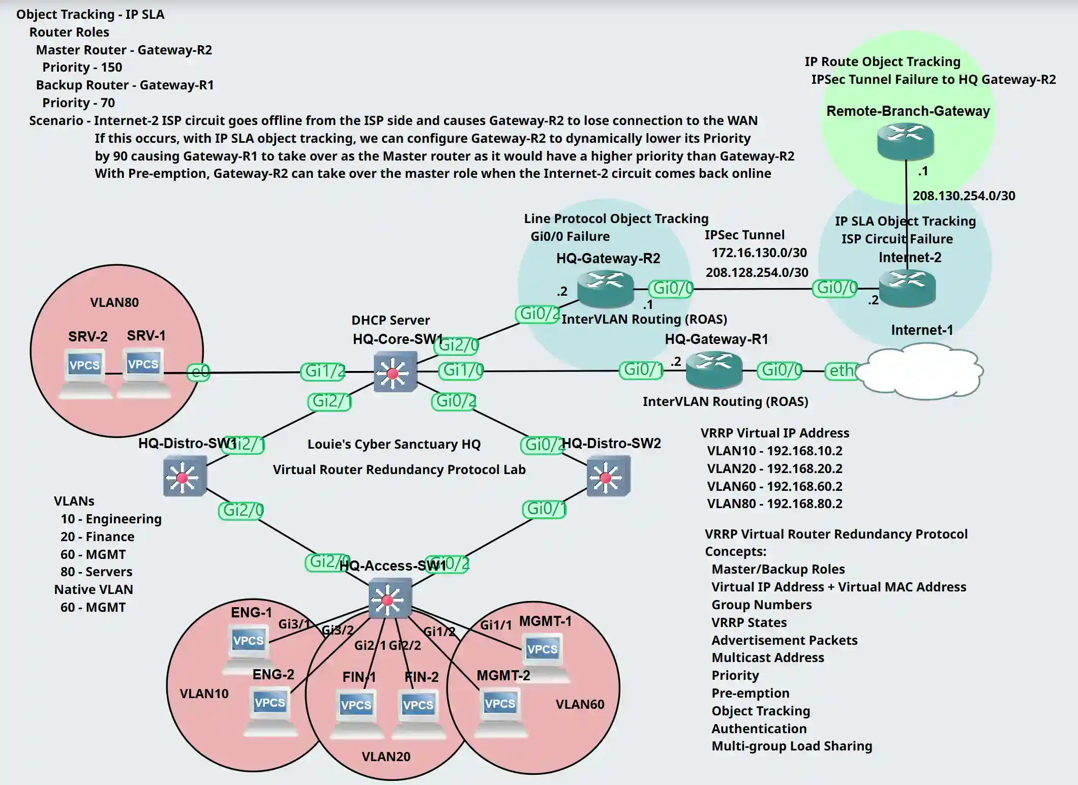
Tracked IP SLA Object Lab Topology
IP SLA is a feature on Cisco devices that allows us to actively monitor and measure the performance of IP networks and services. It enables devices to generate and track various network traffic types such as ICMP, HTTP, DNS, and more.
Scenario: Internet-2 ISP circuit goes offline from the ISP side and causes Gateway-R2 to lose connection out to the WAN. With IP-SLA tracking, we will configure Gateway-R2 to dynamically lower its priority by 90 for all its VLAN VRRP groups, allowing Gateway-R1 to take over as the master router with the higher priority. With Pre-emption enabled on Gateway-R2 by default, Gateway-R2 will retake over as the master router once the Internet-2 circuit comes back online.
Router Roles
- Gateway-R1: Backup role with Priority 70
- Gateway-R2: Master role with Priority 150
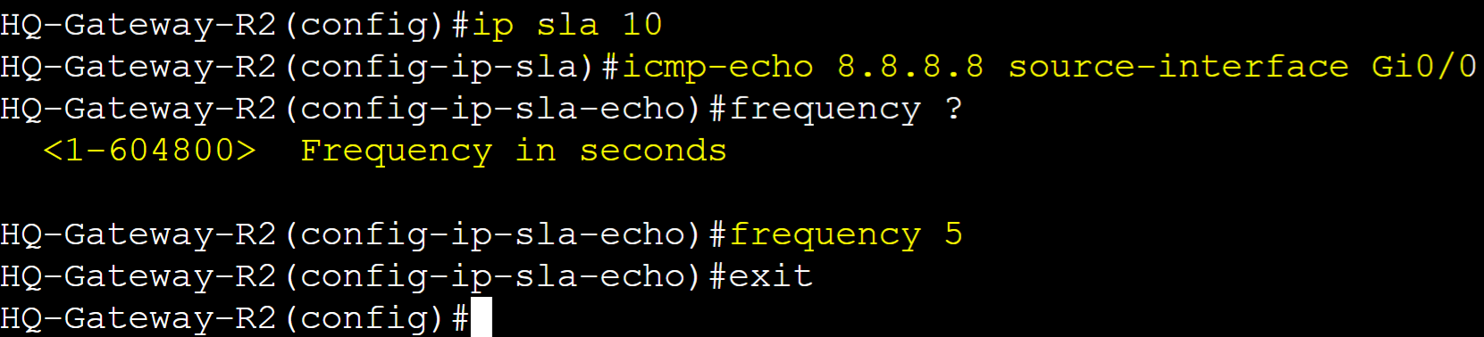
Gateway-R2
Create an IP SLA entry that will be used and applied to a Track object. IP SLA icmp-echo operation to be used to check the reachability status of IP address 8.8.8.8 from the source interface Gi0/0 of Gateway-R2.
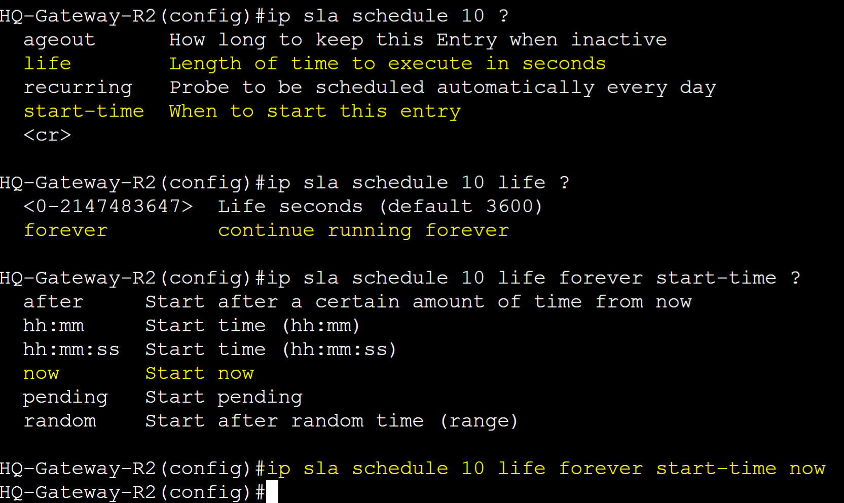
Set a schedule to trigger and start the SLA entry operation.
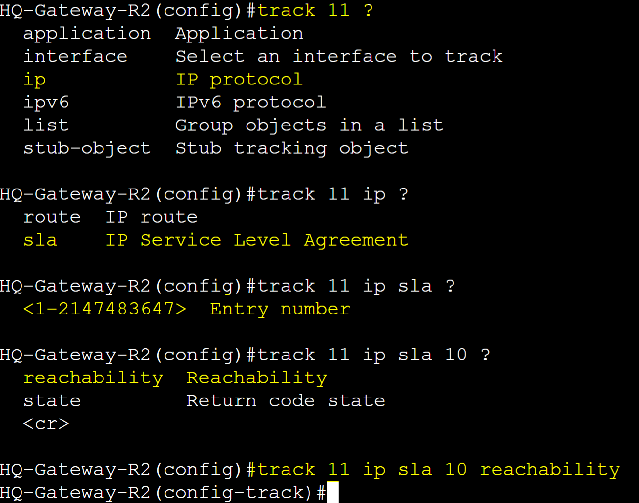
Define the track object to be used by the VRRP groups and associate the IP SLA entry number.
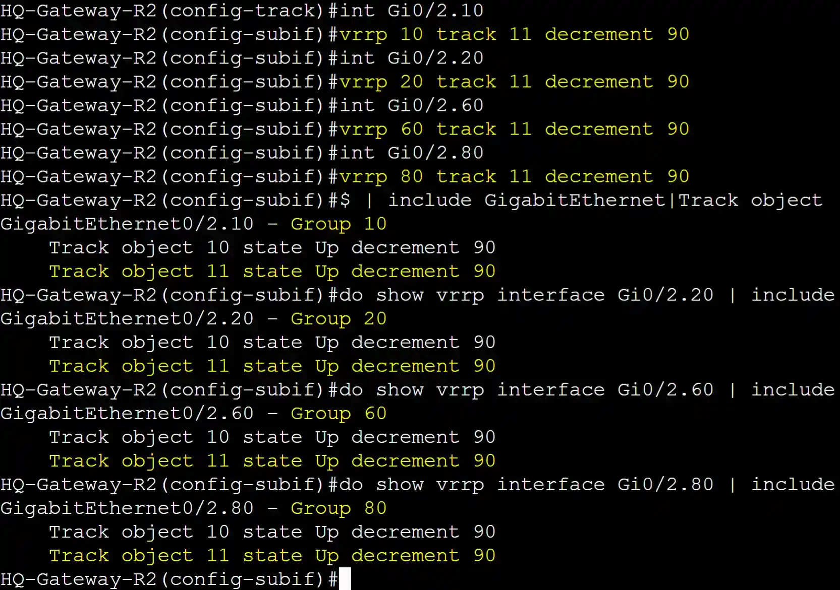
Assign the track object to the VRRP groups and decrement the priority by 90 if the IP SLA entry in the track object goes down.
Testing Failover
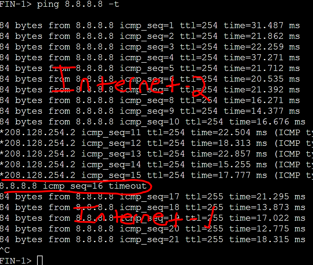
Finance PC in VLAN20 failing over to the ISP Internet 1 circuit off of Gateway-R1 as it took over as the master router.
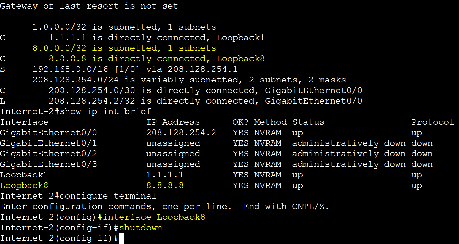
From the Internet 2 ISP router, I've shutdown the Loopback 8 interface with the 8.8.8.8 IP address triggering the IP SLA entry in the track object of Gateway-R2 to go down.
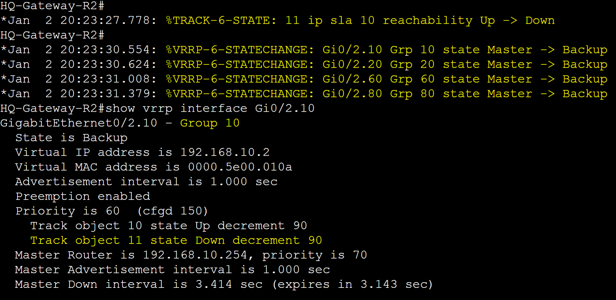
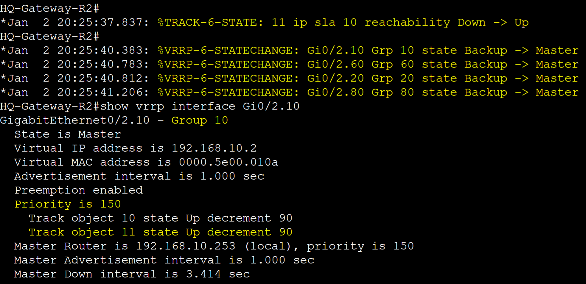
Log messages of Gateway-R2 for the VRRP groups transitioning to the backup role after the reachability failover of the Internet-2 route.
With Preemption, log messages of Gateway-R2 for the VRRP groups re-transitioning over to the master role after the Internet-2 route comes back online.
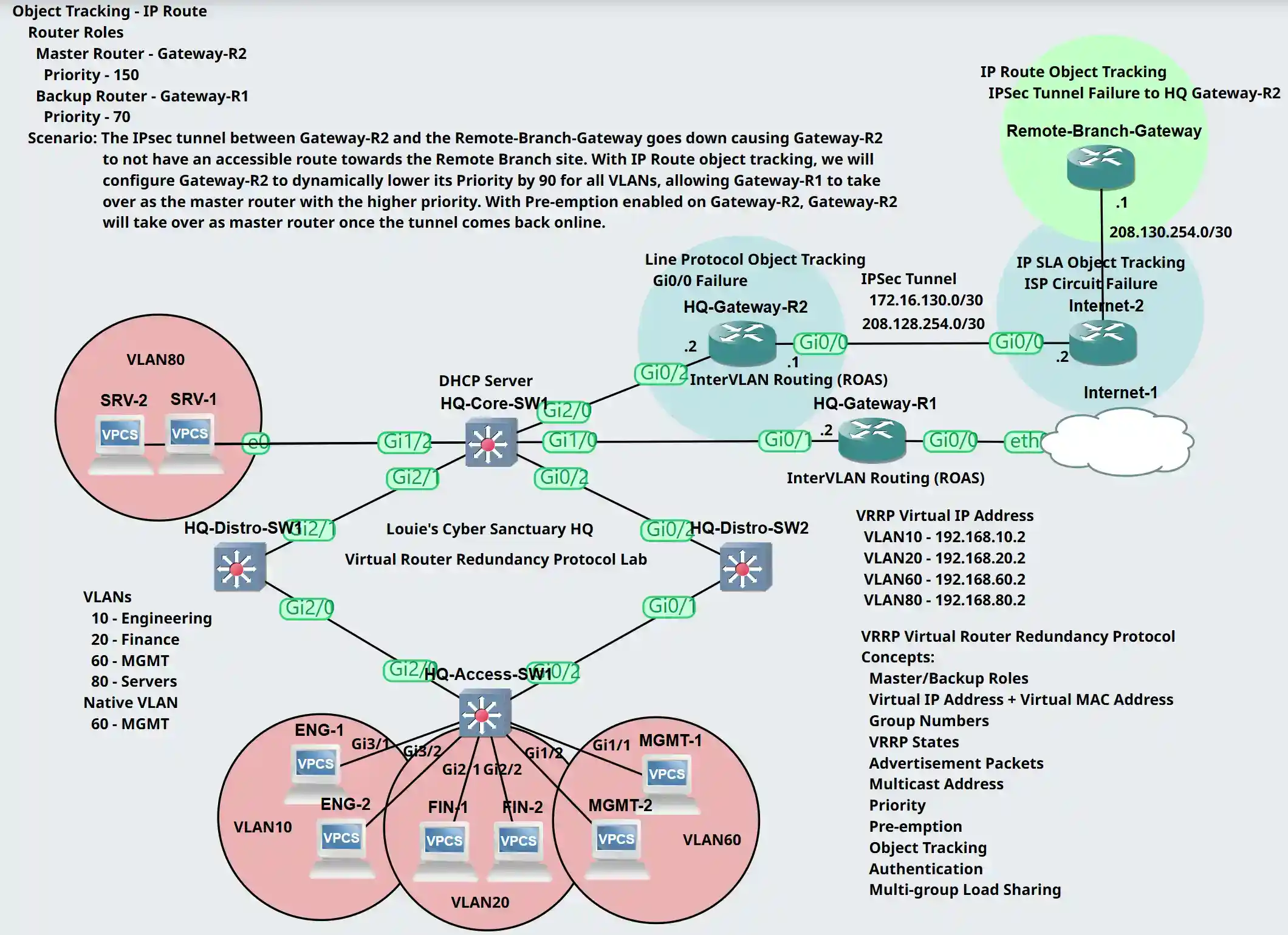
Tracked IP Route Object Lab Topology
IP Route object tracking is used to track the reachability of an IP route in the routing table. An IP route tracked object is considered up when a routing table entry exists for the route and the route is accessible. Use cases for this Object tracking method is with routes learned from dynamic routing protocols or when a down interface results in routes being removed.
Scenario: The IPsec tunnel between Gateway-R2 and the Remote-Branch-Gateway goes down causing Gateway-R2 to not have an accessible route towards the Remote Branch site static networks. With IP route object tracking, we will configure Gateway-R2 to dynamically lower its priority by 90 of all its VRRP groups for each VLAN, allowing Gateway-R1 to take over as the master router with the higher priority. With Pre-emption enabled on Gateway-R2 by default, Gateway-R2 will retake over as the master router once the tunnel comes back online. In a future lesson, we will dive deep in configuring IPsec tunnels.
Router Roles
- Gateway-R1: Backup role with Priority 70
- Gateway-R2: Master role with Priority 150
Gateway-R2 IPSec Configuration
All IPsec configuration steps must be applied to the other side of the IPsec tunnel router or device.
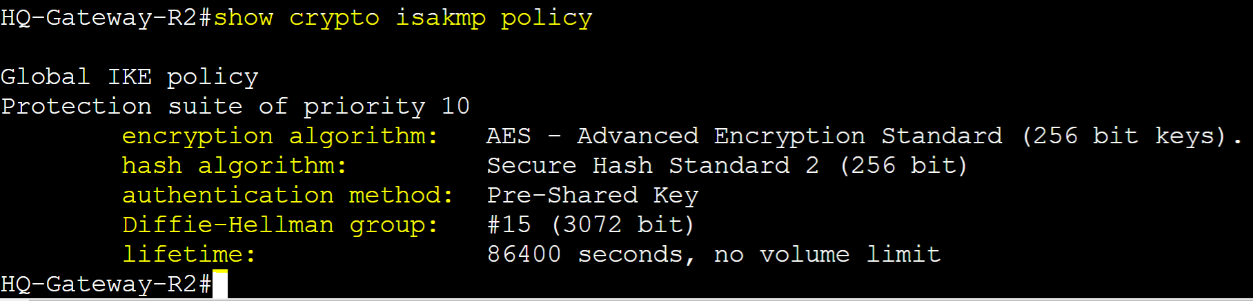
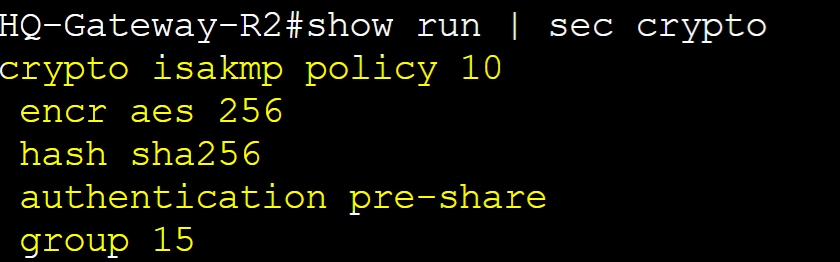
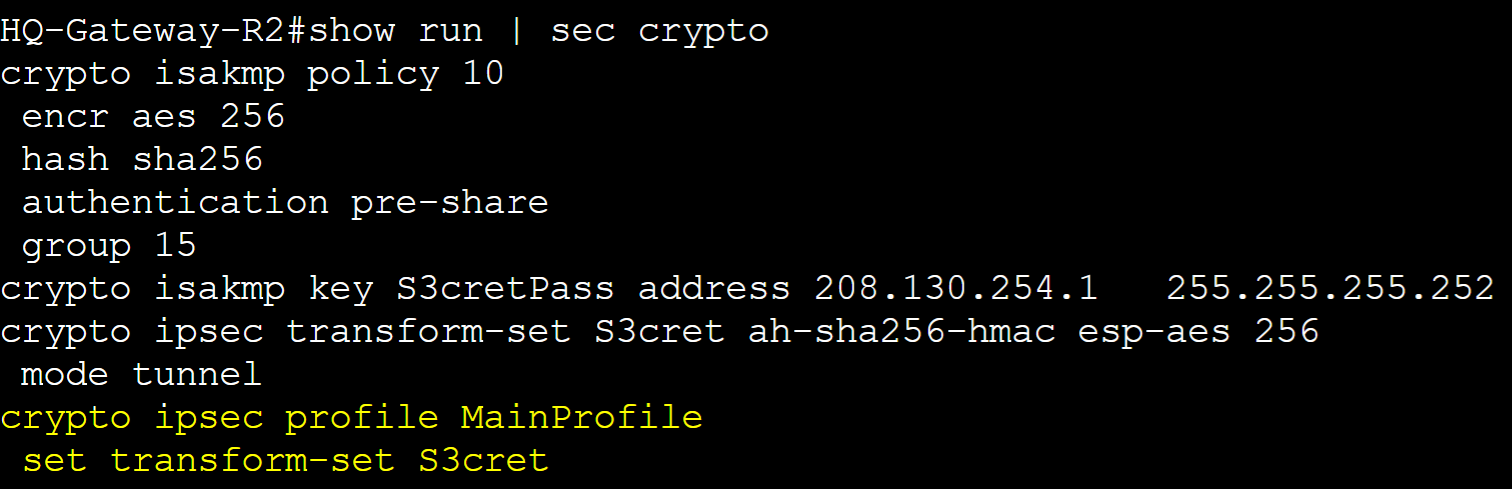
Step 1: Create ISAKMP Phase 1 security parameters to establish tunnel connection with the Remote Branch router
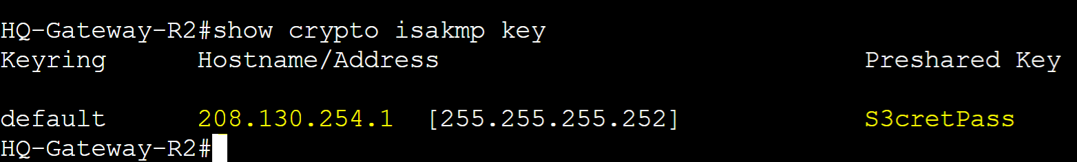
Step 2: Define the phase 1 pre-shared key with the public IP address of the neighbor router
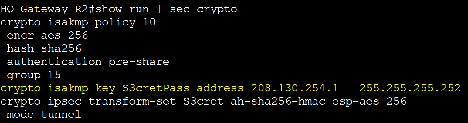
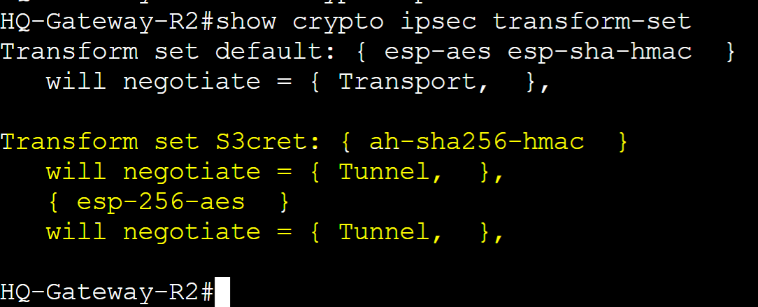
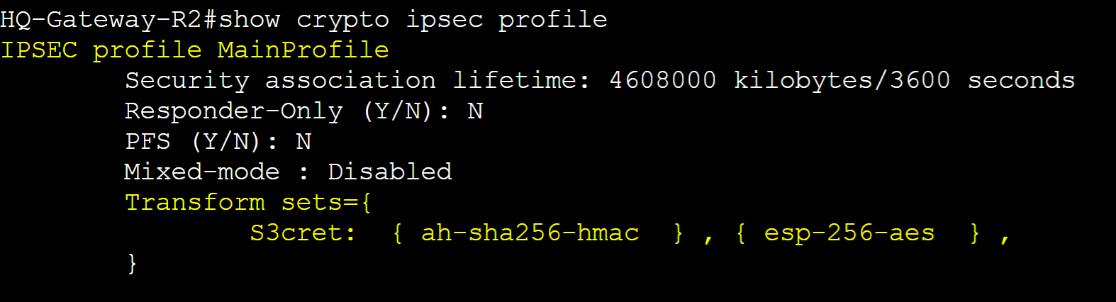
Step 3: Create an IPSec Phase 2 Transform set and assign security parameters to establish an encrypted tunnel with the Remote Branch router
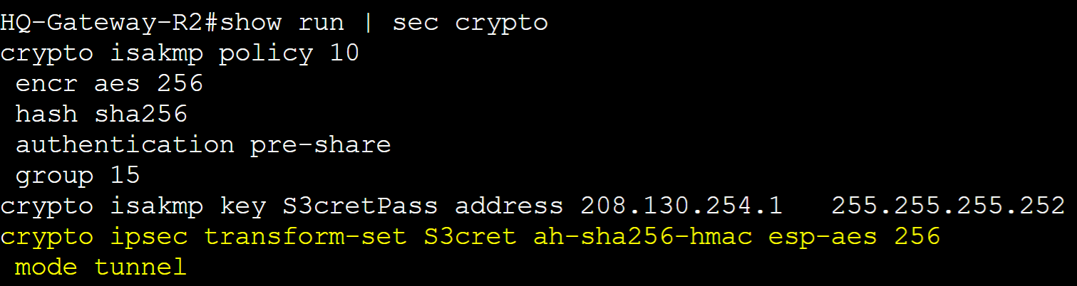
Step 4: Create an IPSec Phase 2 profile and assign the Transform set defined in the previous step
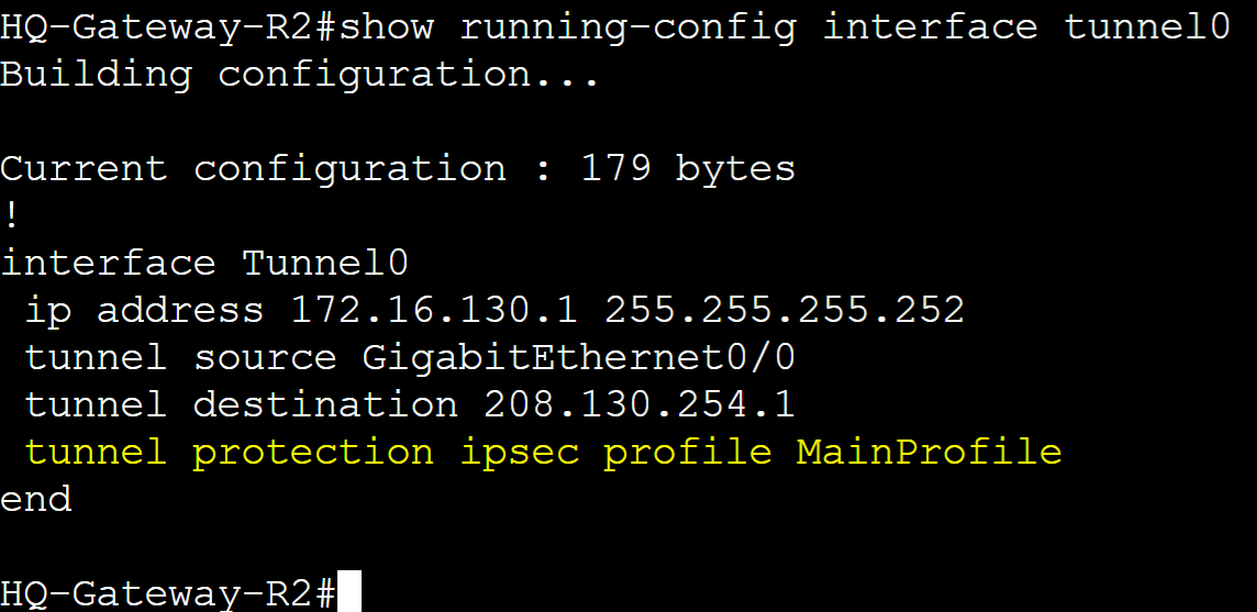
Step 5: Assign the IPsec Profile to the tunnel interface and repeat all steps on the remote router
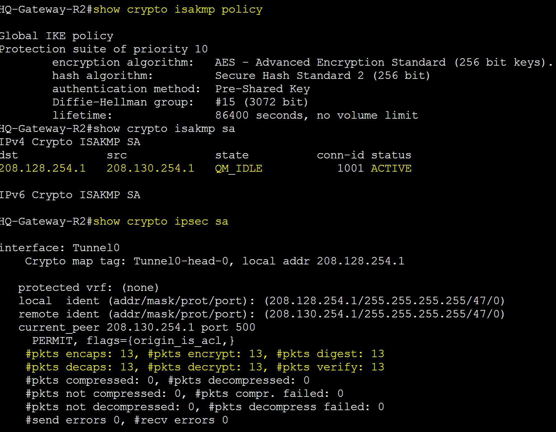
Verification show commands for the active Security Associations of the Phase 1 and Phase 2 ISAKMP process.
Gateway-R2 IP Route Object Tracking
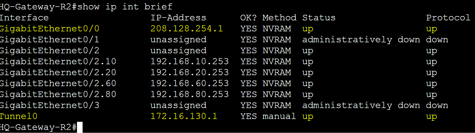
IPsec Tunnel Interface and remote branch routes are active. Goal is to configure IP route tracking so if the tunnel0 interface towards the Remote Branch site router goes down and loses the static remote branch routes 5.5.5.5 and 6.6.6.6, Gateway-R1 will take over as the master router for all VRRP groups during the failover period.
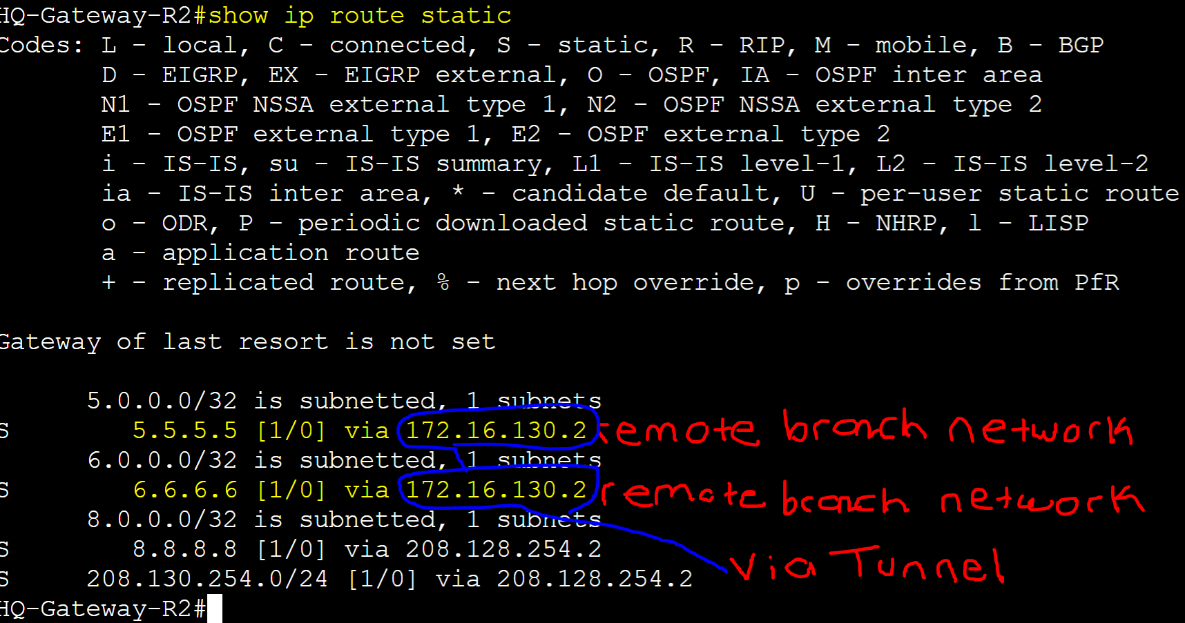
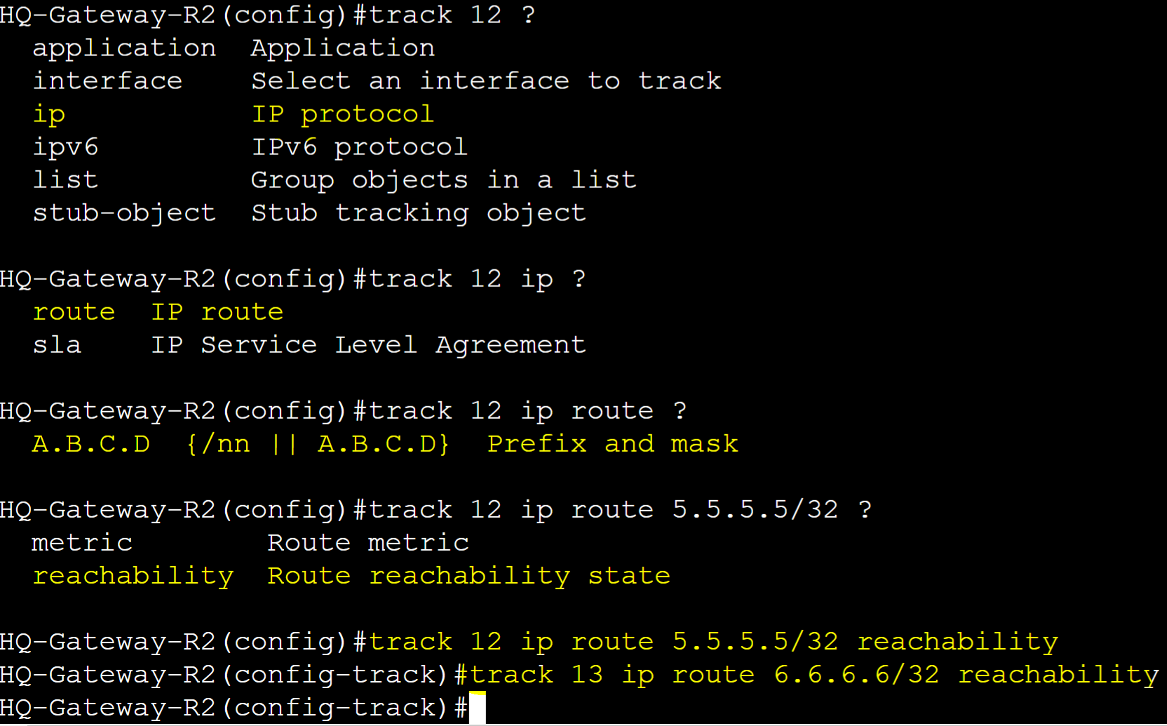
Define the two track objects to track the IP route reachability status of networks 5.5.5.5 and 6.6.6.6 in the Gateway-R2 routing table towards the Remote Branch site. Track objects will trigger only if the routes are removed from the routing table.
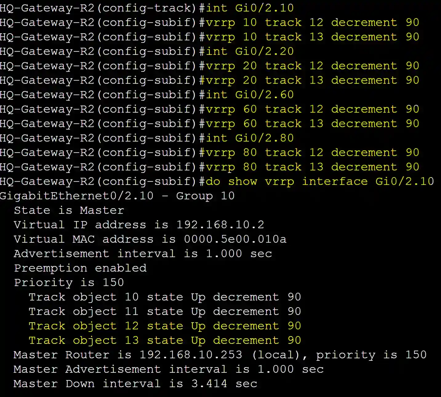
Applying both IP route track objects to all VRRP groups decrementing the priority by 90 if the static routes are removed from the routing table.
Testing Failover
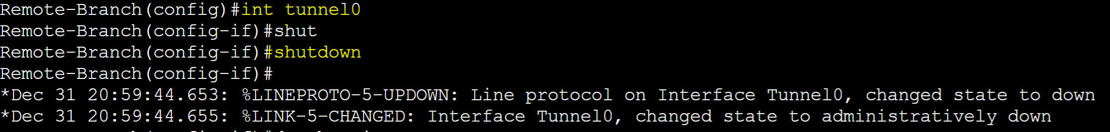
On the remote branch gateway router, I tested the failover event by shutting down the Tunnel interface towards Gateway-R2 causing Gateway-R2 to lose the remote branch routes of 5.5.5.5 and 6.6.6.6.
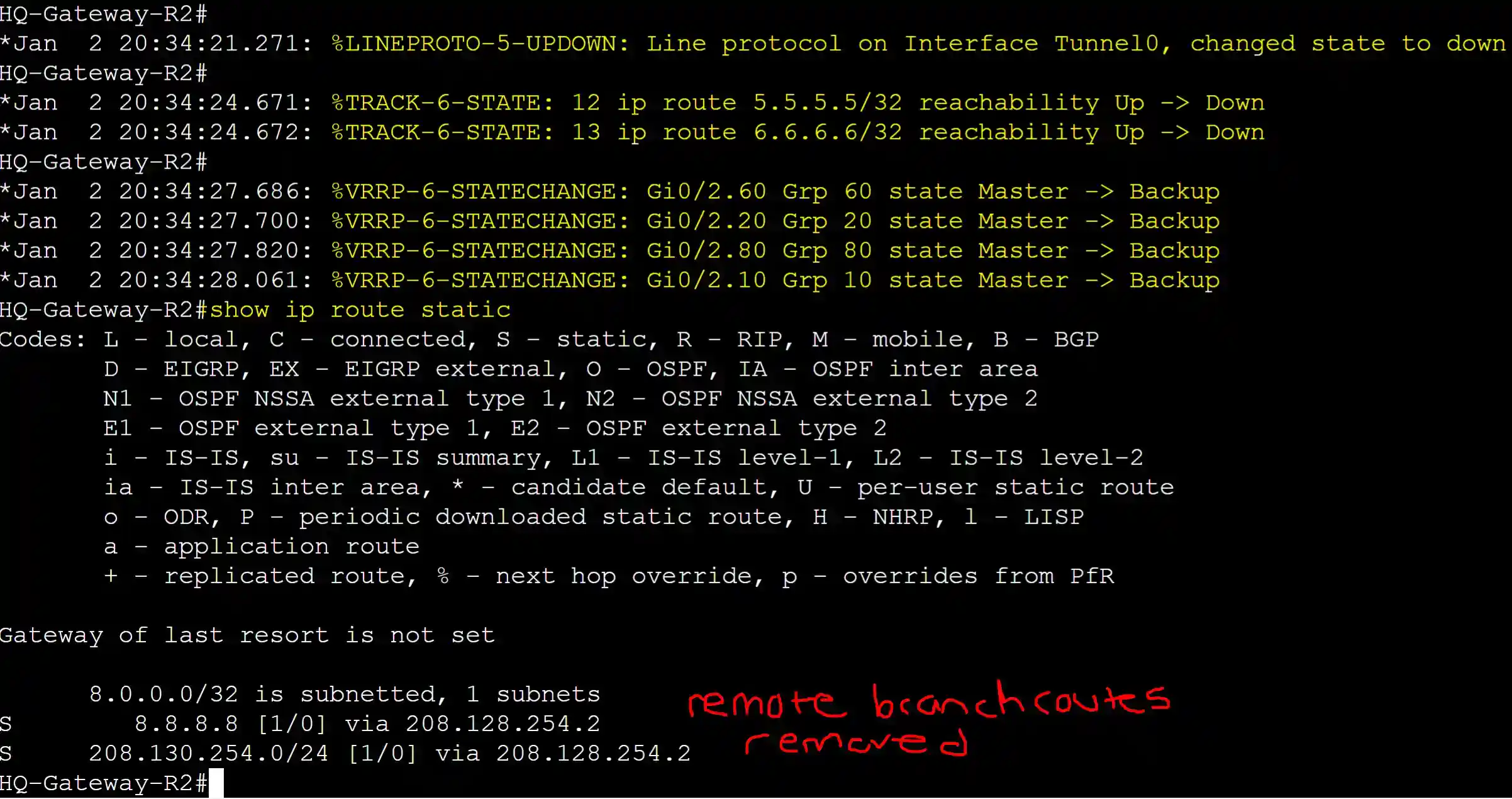
Gateway-R2 transitioned to the backup role after losing the remote branch networks via the tunnel interface.
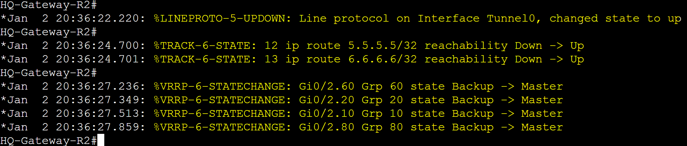
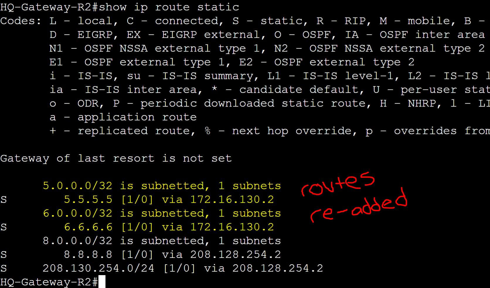
With Preemption enabled, Gateway-R2 re-took over as the master router for all its VRRP groups once the Tunnel interface came back up. The remote routes have been re-added to the Gateway-R2's routing table.
Multi-Group Load Sharing
Multi-group Load Sharing is a method to distribute traffic across multiple VRRP groups in a way that allows for load balancing between master routers. Without configuring multiple groups for load sharing, by default, VRRP does not provide load balancing for a single VRRP group. Configuring multiple groups can provide improved load distribution by reducing the traffic load on a single router.
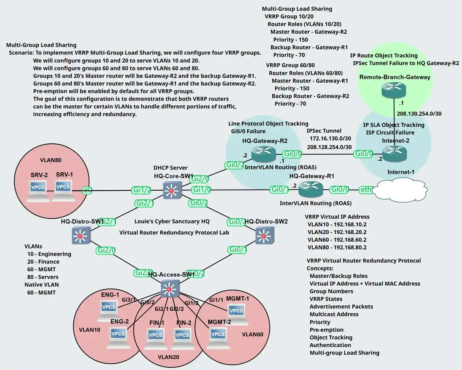
Multi-Group Load Sharing Lab Topology
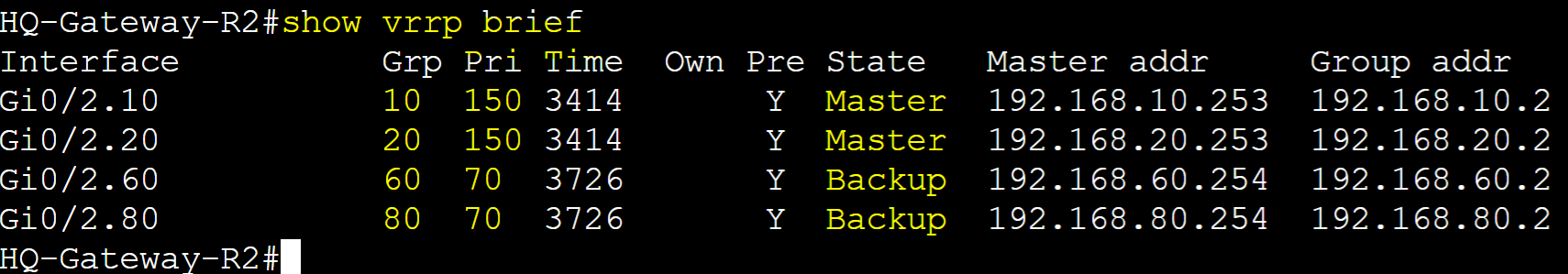
Scenario: To implement VRRP Multi-Group Load Sharing, we will configure four VRRP groups. VRRP group 10 and 20's master router will be Gateway-R2 and the backup router Gateway-R1. VRRP group 60 and 80's master router will be Gateway-R1 and the backup router Gateway-R2. Groups 10 and 20 will serve VLANs 10 and 20 whereas Groups 60 and 80 will serve VLANs 60 and 80. Pre-emption will be enabled by default for all groups. The goal of this lab exercise is to demonstrate that both VRRP routers can be the master for certain VLANs to handle different portions of traffic, increasing efficiency and redundancy.
(Group 10/20) Router Roles
- Gateway-R1: Backup with priority 70
- Gateway-R2: Master with priority 150
(Group 60/80) Router Roles
- Gateway-R1: Master with priority 150
- Gateway-R2: Backup with priority 70
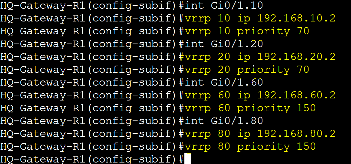
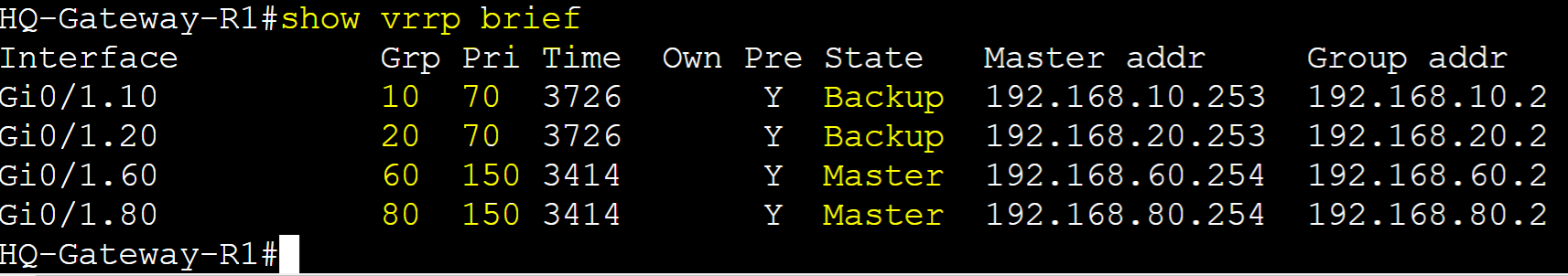
Gateway-R1
Configure groups 10 and 20 as the Backup role on Gateway-R1 and Master for groups 60 and 80.
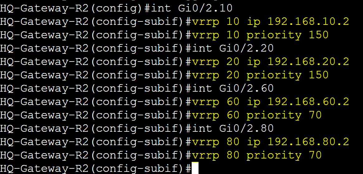
Gateway-R2
Configure groups 10 and 20 as Master role on Gateway-R2 and Backup for groups 60 and 80.