Load Balancing
Overview:
- MST or Multiple Spanning Tree is a variation of STP that is designed to allow the grouping and mapping of VLANs into a single Spanning Tree instance
- MST can improve network efficiency and simplify the configuration of complex networks managing VLAN STP instances
- With the ability to group VLANs into fewer instances, each STP instance can be defined to take a different network path upstream to prevent under utilization of certain links in the topology
Lab Topology
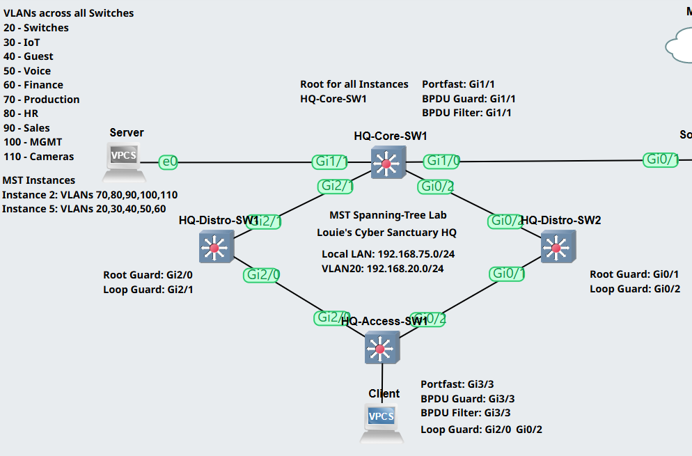
MST Planning and Configuration
MST brings a new concept of Regions that place switches in an MST Spanning Tree domain.
In this lab exercise, all four switches in the lab topology will be placed in a single region sharing common characteristics just like PVST or RPVST+.
There are certain matching parameters that need to be defined on each switch in the region to properly group together switches to a region.
Matching Parameters:
- Name
- The region name that is defined on a per switch basis
- For any switch to be in the same MST region, they must have an identical MST name
- Revision number
- An attribute of an MST region to distinguish different MST regions on a network
- For any switch to be in the same MST region, they must have an identical Revision number
- Instance number
- The Spanning Tree instance number that is associated with VLAN mappings
- Each region can support up to 65 MST instances
- You can only assign a unique VLAN to one instance at a time
- For any switch to be in the same MST region, they must have an identical Instance to VLAN mapping
- Note: For any VLANs that are not mapped to a created instance, they will stay mapped into the default instance 0
- Note: Instance 0 is also known as the Common Spanning Tree or (IST) and the importance of the IST will be discussed in the 'BPDUs in an MST Region' section
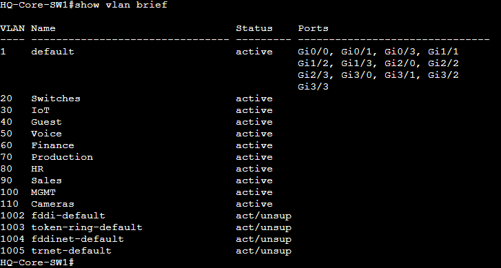
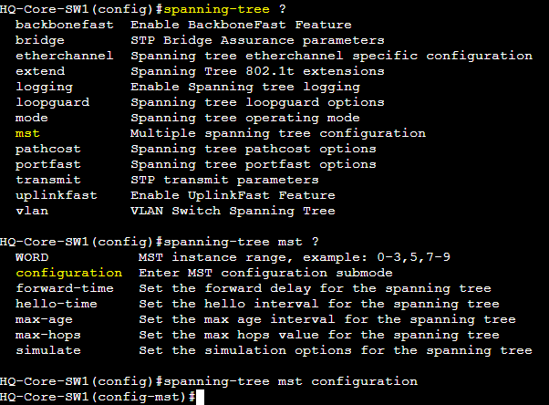
Configuration
Verification of the 10 unique configured VLANs on the core switch.
Two MST instances will be created with 5 VLANs each. Redirect to MST configuration mode to define these instances.
Notes:
- Command to prompt MST configuration mode: 'spanning-tree mst configuration'
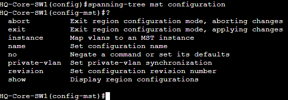
- From MST configuration mode, the matching parameters can be defined
Matching Parameter Options:
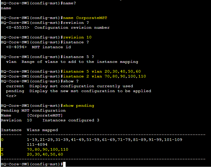
- Region Name: CorporateMST
- Revision Number: 10
- Instance Number: 5
- Mapped VLANs: 20,30,40,50,60
- Instance Number: 2
- Mapped VLANs: 70,80,90,100,110
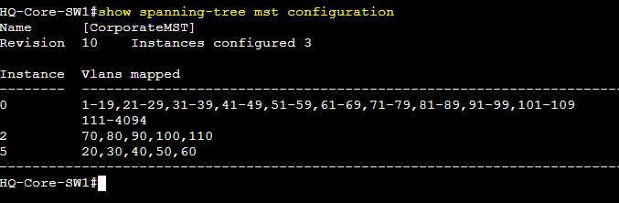
To save the MST configuration, exit out of MST configuration mode and verify with the command 'show spanning-tree mst configuration'.
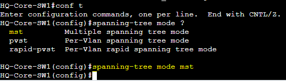
Set the Spanning-Tree mode to MST and repeat the previous steps on all switches in the region.
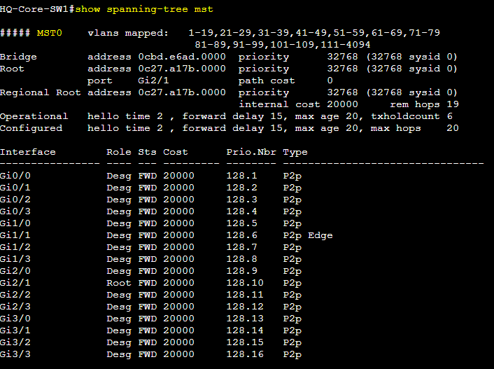
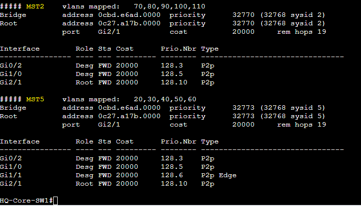
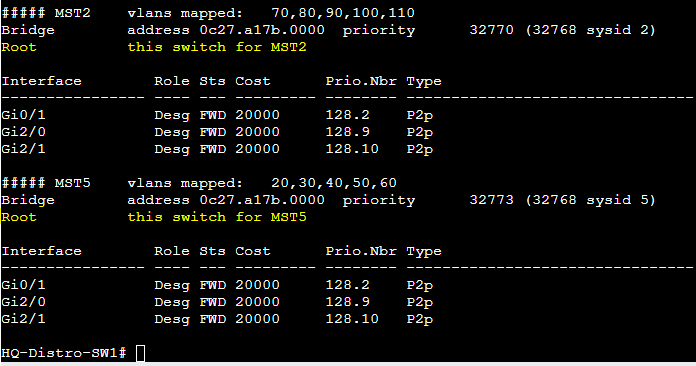
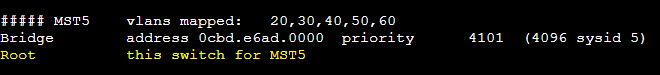
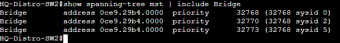
Verifying the MST spanning tree instances you can see there are 3 MST instances: Instance 0, 2, and 5 with their VLAN mappings.
MST Root Modification
By default, the root bridge with the lowest BID consisting of the priority and MAC address will become the Root Bridge for all MST instances including instance 0.
In this lab exercise, we will set HQ-CoreSW1 as the Root Bridge for all MST instances.
MST utilizes the Long cost method in calculating the port costs towards the Root Bridge and is the recommended method for today's networks.
Notes:
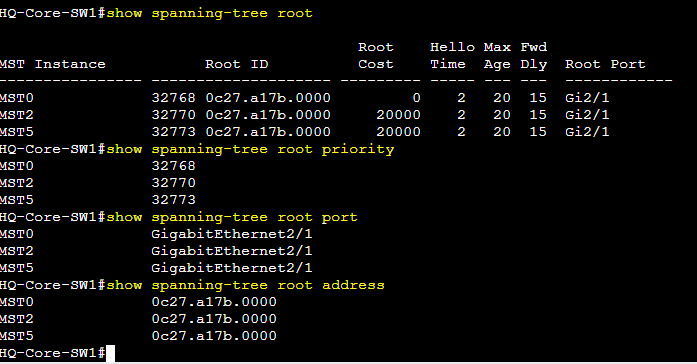
- From the HQ-CoreSW1, I verified the priority currently set on the switch and from the root port we can see that HQ-CoreSW1 is not the current Root Bridge for the MST domain
- From the 'show spanning-tree root port' command, I can see that the least cost towards the current root bridge is via root port Gi2/1
Notes:
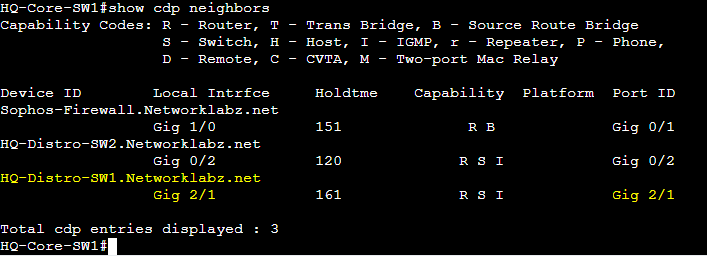
- I've issued the 'show cdp neighbors' command to see which device is connected to the Gi2/1 root port of HQ-CoreSW1
- I've identified that the switch I need to analyze is HQ-DistroSW1 as it's suspected to be the current Root Bridge for the MST domain
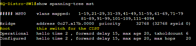
I've verified that HQ-DistroSW1 is the current Root Bridge for all instances and the next lab exercise step would be to configure HQ-CoreSW1 as the Root Bridge for all MST instances.
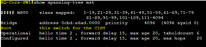
I've issued the command 'spanning-tree mst 0,2,5 priority 4096' to give HQ-CoreSW1 a more preferred priority value to become elected as the new Root Bridge for the following MST instances.

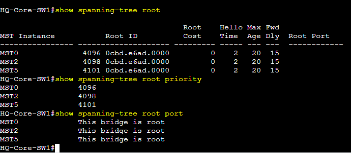
I've verified that HQ-CoreSw1 is the Root Bridge for all MST instances.

Additional Spanning Tree show commands to verify that HQ-CoreSW1 is the current Root Bridge for all MST instances.
BPDUs in an MST Region
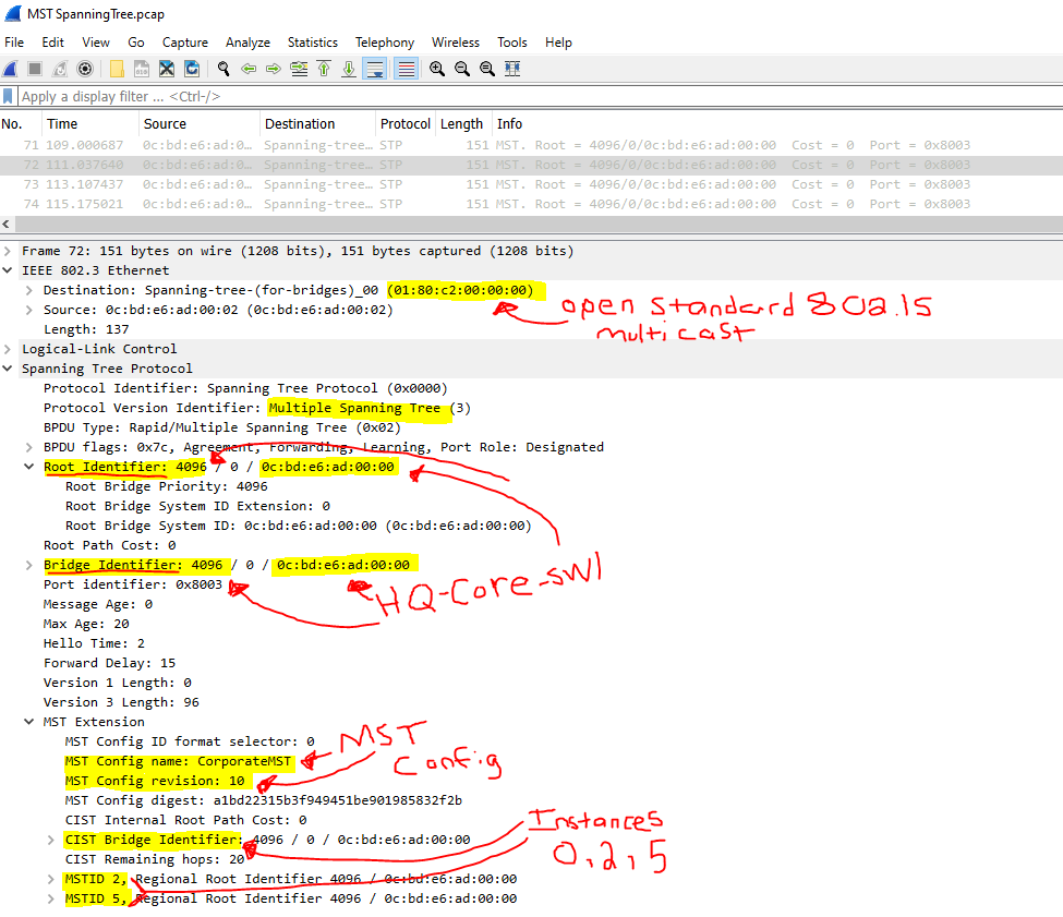
In an MST Region, the IST or Instance 0 Root Bridge is responsible for all BPDUs consisting the info of all instances.
MST instance 0 carries BPDUs for all VLANs within a region, regardless of which MST instance they are mapped to.
MST Packet Capture Example
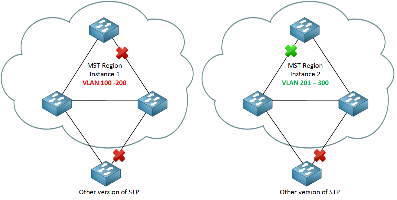
MST Regions Connecting to Non-MST Switches
If an MST region is connected to a Non-MST switch, Edge MST switches will advertise a cost of 0 to the outside Non-MST region switches.
In the MST lab topology, between the Edge MST switches and the Non-MST switch, legacy PVST or RPVST+ BPDUs are exchanged as MST BPDUs and other STP standard BPDUs are not compatible with one another.
With standard STP rules still in place, if a Non-MST switch has redundant links towards the edge MST switches, the tie-breaker for the active Non-MST root port will commonly be the lowest BID value amongst the neighbor edge MST switches.
We will look at a scenario to grasp this concept by adding a Non-MST switch into the lab topology.
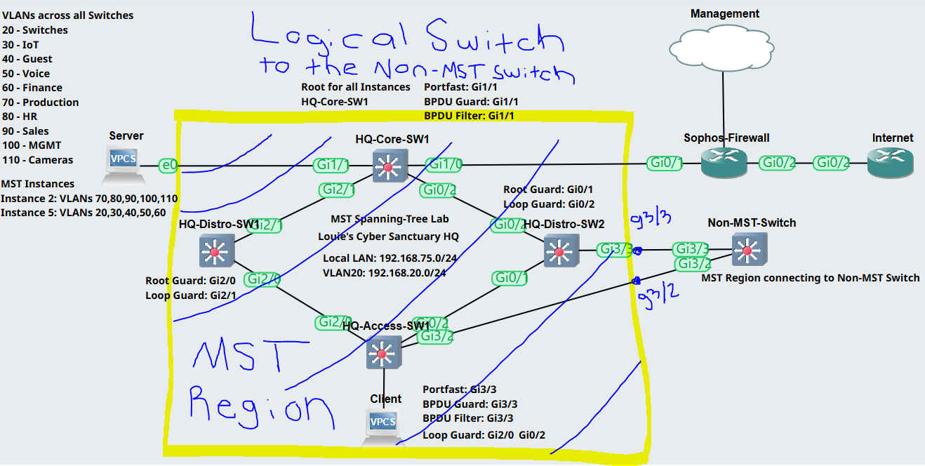
To better understand this concept, as the Non-MST switch has no understanding of standard MST rules and guidelines; from the perspective of the Non-MST switch, the MST region appears to be one big logical switch it is connected to.
Notes:
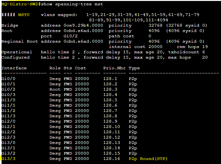
- Verifying the Spanning-Tree state of HQ-DistroSW2, we can see that the interface Gi3/3 connecting towards the Non-MST switch has fallen back to the older standard STP port (Bound (STP))
- The reason for this is because the legacy STP BPDUs are not compatible with MST BPDUs thus the MST switch falls back to the older standard
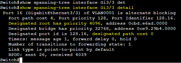
To confirm the MST-switches advertising a cost of '0' to reach the Root bridge towards the Non-MST switch, I've issued the following interface show commands on the Non-MST switch to identify and confirm the designated path cost of 0.

Root Port Modification from Non-MST switches to MST Region
Looking back at the previous section, Non-MST switches choose the redundant link leading to the edge MST switch with the lowest BID value by default for root port designation.
In this lab exercise, we will modify the root port selection from the Non-MST switch connecting to the MST region.
Notes:
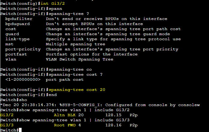
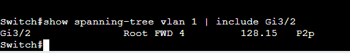
- In this example, the Non-MST switch chose interface Gi3/2 as its root port because the BID value of HQ-AccessSW1 is a more preferred (lower) value than HQ-DistroSW2's BID
- Both MST switches are using the default priority value of 32768 so the tie breaker was the lowest MAC address of the BID value

Notes:
- To make the link to HQ-DistroSW2 the more preferred route for the Non-MST switch to take, we will modify the Non-MST switch's Gi3/2 port path cost to a less preferred value (with a higher value being worse)
- After modifying the Gi3/2 port leading towards HQ-AccessSW1 to a less preferred cost value, the new root port is now Gi3/3 towards HQ-DistroSW1