Inter-VLAN Routing
Sections:
Overview:
- After learning about VLANs, we know that hosts in one VLAN are isolated from hosts in other VLANs
- Inter-VLAN Routing is the process of forwarding network traffic from one VLAN to another VLAN through the use of a layer 3 device
- In today's networks it's essential for networks that require segmentation and security through the use of VLANs to also have the ability to exchange data across VLANs in certain scenarios
- We will discuss three methods to implement Inter-VLAN Routing in which each have their pros and cons
- Options
- Legacy Inter-VLAN Routing using multiple router interfaces
- (ROAS) Router on a Stick
- (SVIs) Layer 3 switches using SVIs
Inter-VLAN Routing Options
Legacy Inter-VLAN Routing
The original Inter-VLAN routing method utilized an external router with multiple Ethernet interfaces configured in their own respective VLAN to support the hosts in that VLAN.
Pros
- The only upside to this method is that each VLAN would get its own dedicated Ethernet link to utilize the full bandwidth link capacity vs sharing the bandwidth across all VLANs in the ROAS method
- However, even if VLANs get their dedicated link, underutilization would also be a concern
Cons
- The downside with this method is the severe limitation of Ethernet Interfaces built onto routers and therefore not a scalable solution moving forward to today's networks with multiple VLANs
(ROAS) Router on a Stick
In a ROAS configuration, a single external router is used to route traffic between VLANs on a network. A single physical link is logically sub-divided into sub interfaces each corresponding to a different VLAN. The router uses 802.1Q encapsulation to distinguish different VLANs.
The physical link towards the switch is typically configured as a trunk link for the switch to carry multiple VLANs.
With sub-interfaces on the router, each is configured with its own IP address that will act as the default gateway for devices in that VLAN.
Pros
- Cost Effective
- Using a single router interface to handle multiple VLANs reduces the need to invest in multiple physical interface cards on a router
Cons
- Performance
- Overutilization of the shared bandwidth could become an issue if there is an excess of traffic load across different VLANs
- Scalability
- The more VLANs are added, configuration can become a growing complexity to manage

(SVIs) Layer 3 switches using SVIs
In a Layer 3 switch SVI configuration, a layer 3 switch is used to route traffic between VLANs through SVIs or Switched Virtual Interfaces. SVIs represent a either a VLAN gateway for hosts or a management interface for the switch and functions similarly to a router's interface but on a switch. The switch associates each VLAN with an IP address serving as the default gateway for hosts in that VLAN.
Pros
- Faster than ROAS
- Inter-VLAN routing on a Layer 3 switch is supported by hardware switching and routing vs software based routing on routers
- Low Latency
- Routing between VLANs on a Layer 3 switch occurs at wire speed, minimizing the latency compared to routing on traditional routers
Cons
- Cost Difference of Layer 2 to Layer 3 Switches
- Layer 3 switches generally cost more than layer 2 switches due to the added functionality and features
- Limited Functionality
- Layer 3 switches may not have all available features of dedicated routers such as NAT but can be passed down towards a router or firewall to apply these features

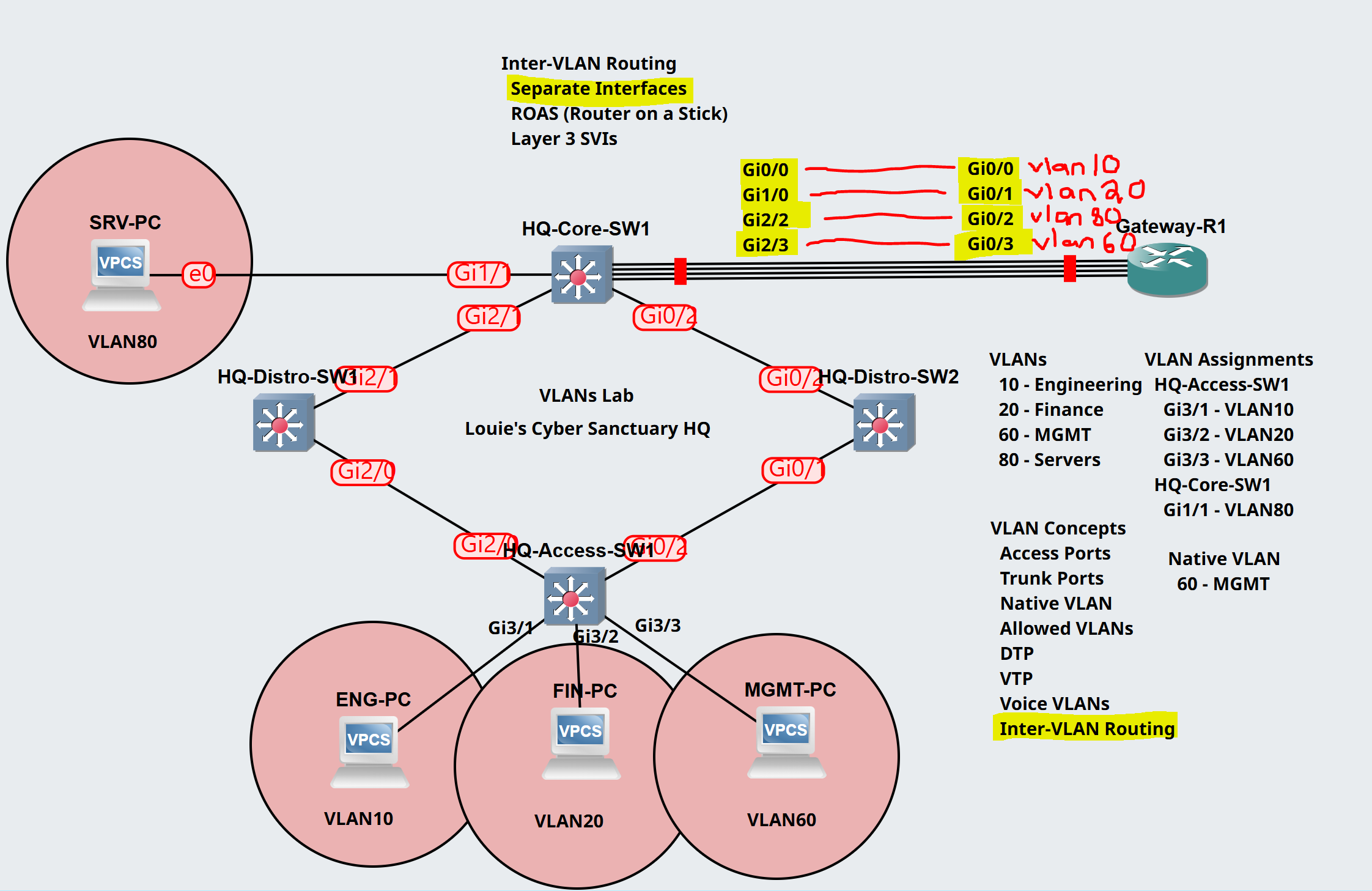
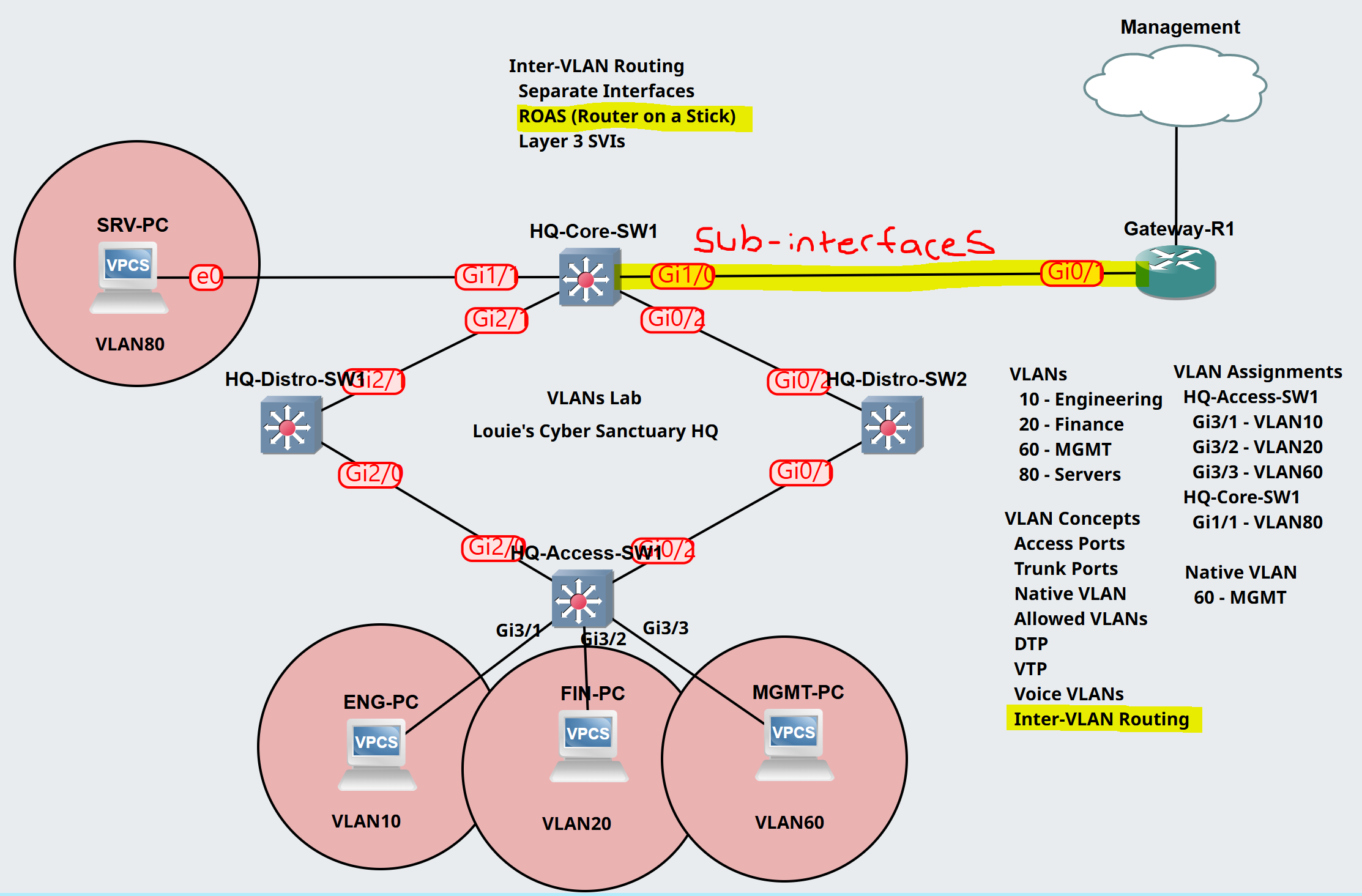
Lab Topology
Scenario:
- In this lab scenario, I will configure Inter-VLAN routing using the legacy method with separate router interfaces
- Trunk links have already been configured on the downstream connections from the Core switch in the trunking lesson
- I will assign the following core switch uplink interfaces with the appropriate access port VLAN towards the router
- Gi0/0 - VLAN 10 (Engineering)
- Gi1/0 - VLAN 20 (Finance)
- Gi2/2 - VLAN 80 (Servers)
- Gi2/3 - Native VLAN 60 (MGMT)
- I will assign IP addresses on each VLAN PC and issue a ping towards the router gateway
- I will analyze a packet capture on each router interface for incoming ICMP packets from the PCs in each VLAN

Legacy Inter-VLAN Configuration
HQ-Core-SW1
Verify active trunks & vlans.

Assign access ports to the core switch uplinks towards the router and verify.

Gateway-R1
Assign IPs to the router interfaces supporting the default gateways of all VLANs.

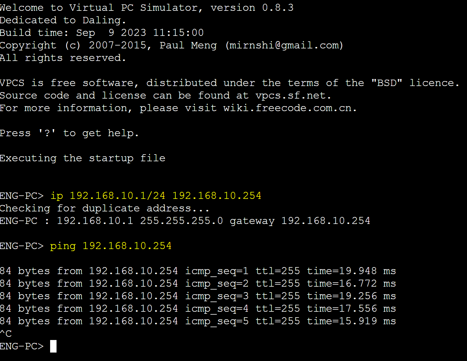
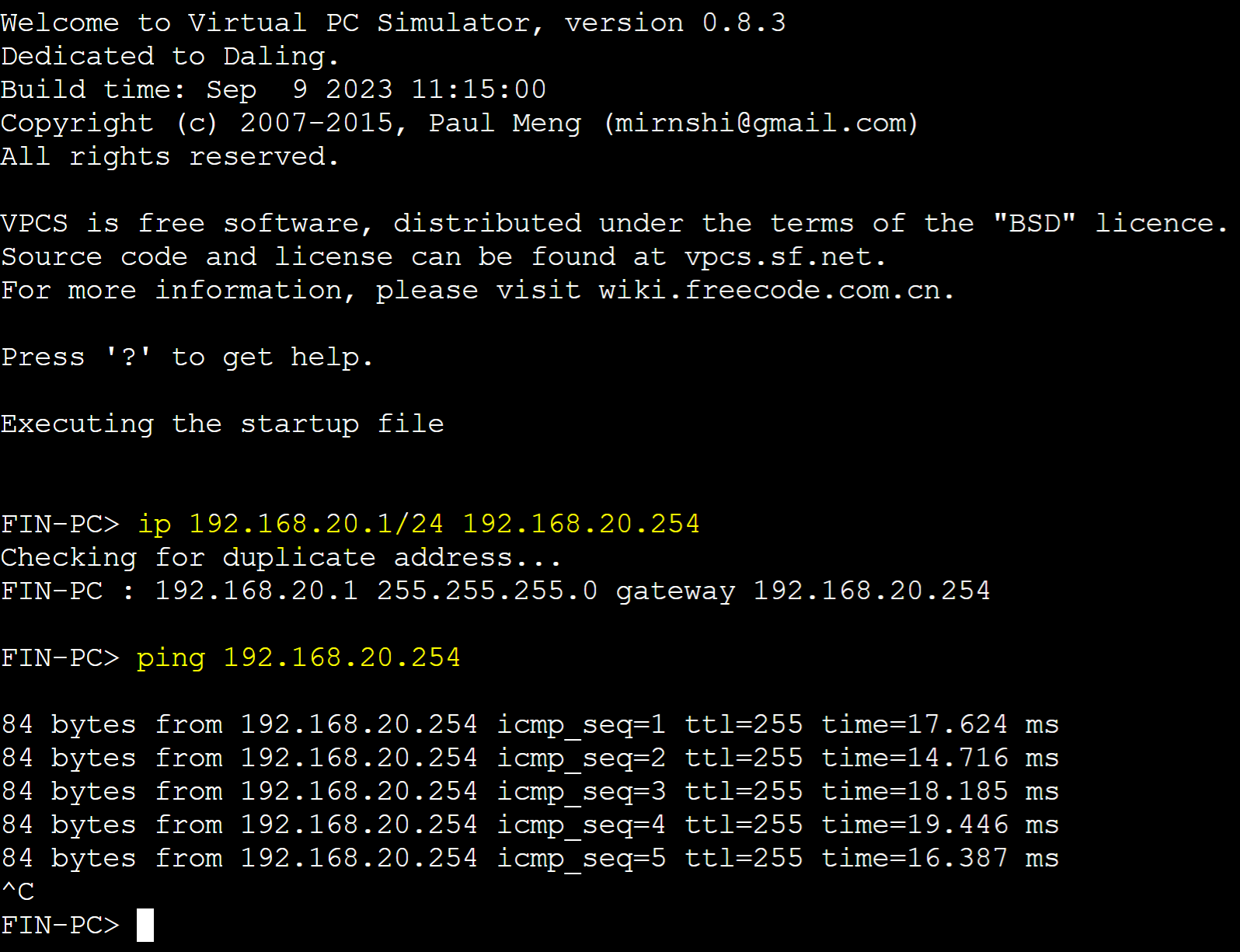
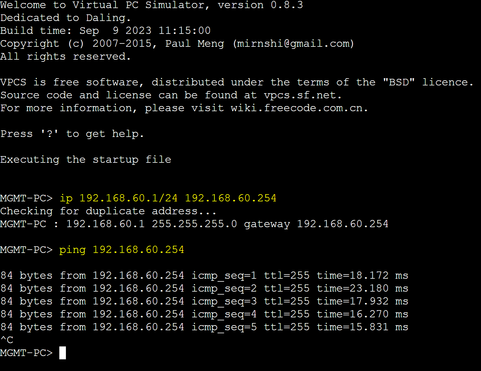
PC Ping Tests to Gateways
VLAN 80 (Servers)

VLAN 10 (Engineering)
VLAN 20 (Finance)
VLAN 60 (MGMT)
Packet Captures
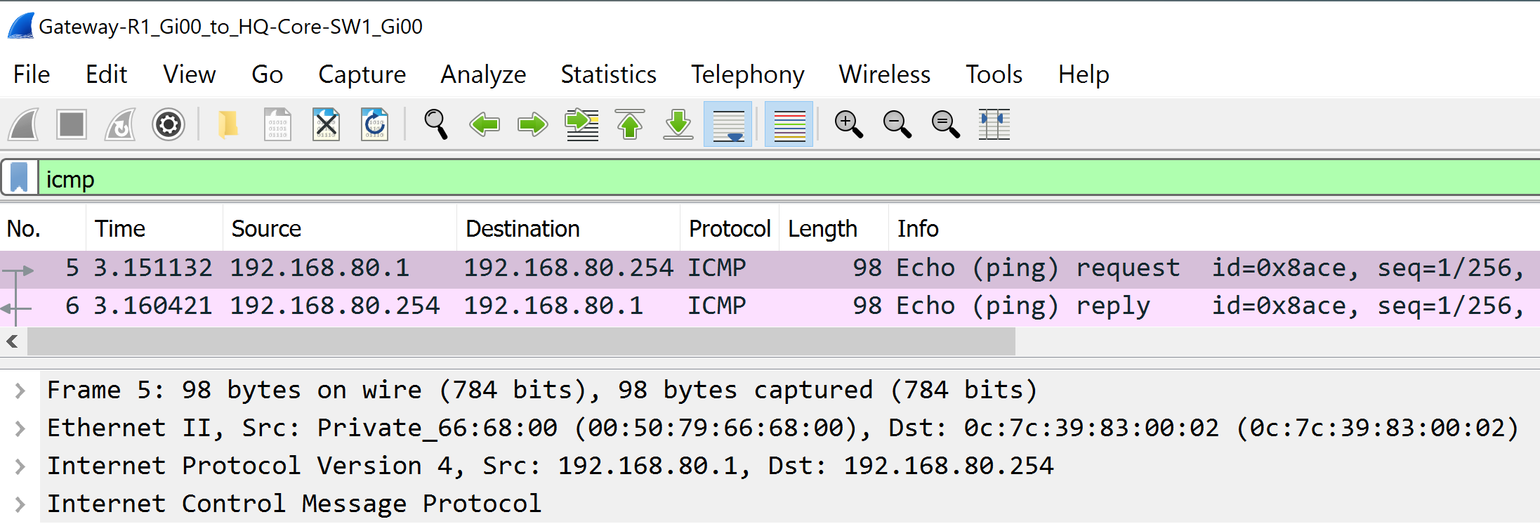
Gateway-R1 Gi0/0 (VLAN 10)

Gateway-R1 0/1 (VLAN 20)

Gateway-R1 Gi0/2 (VLAN 80)
Gateway-R1 Gi0/3 (VLAN 60)
(ROAS) Inter-VLAN Routing Configuration
Scenario:
- In this lab scenario, I will configure Router on a Stick Inter-VLAN routing using sub-interfaces of the physical router
- I will configure an upstream trunk link from the Core switch towards the router to carry all four VLANs
- I will configure sub-interfaces on the router using 802.1Q encapsulation to differentiate between the different VLANs
- The router sub-interface for VLAN 60 MGMT will be set to the native VLAN and therefore traffic from VLAN 60 will not be tagged
- Downstream trunk links from the Core switch have already been configured in the Trunking lesson
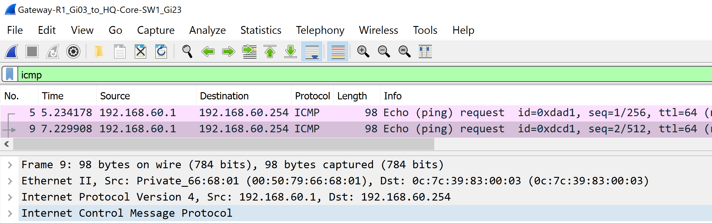
- I will analyze a packet capture to look for the 802.1Q VLANID tags from incoming ICMP messages from each PC/VLAN
HQ-Core-SW1
Assign uplink of the core switch a trunk role with the allowed vlans.

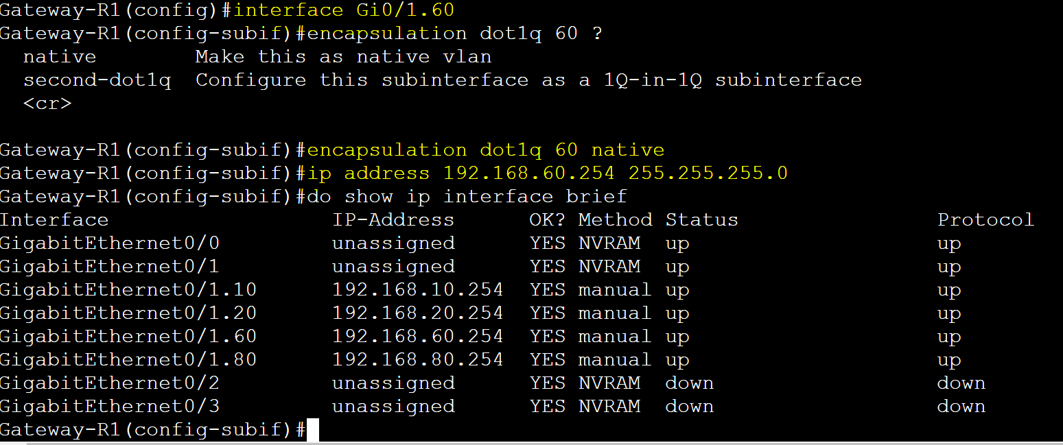
Gateway-R1
Configure sub-interfaces on the router and assign them a vlan and IP.
Sub-interfaces are configured by specifying the physical link identifier followed by a period then a number. Specifying the vlan number is best practice.
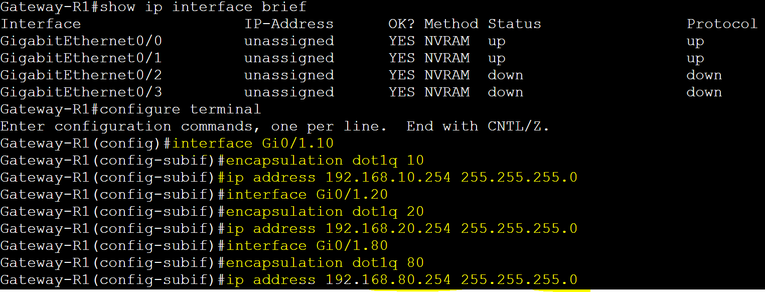
Sub-interface for VLAN 60 is set to the native vlan.
PC Ping Tests to Gateways
VLAN 80 (Servers)

VLAN 10 (Engineering)

VLAN 20 (Finance)

VLAN 60 (MGMT)

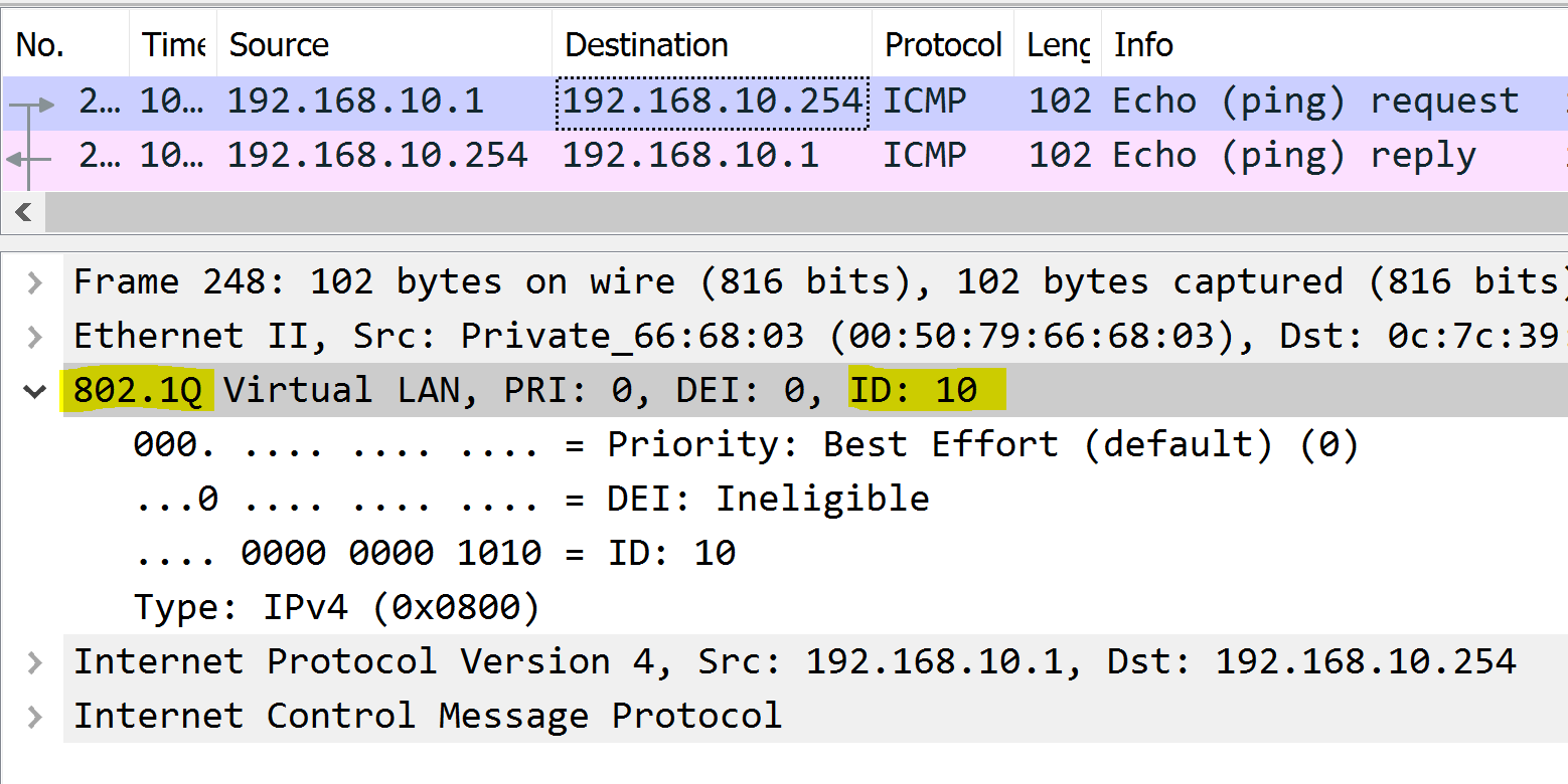
Packet Captures
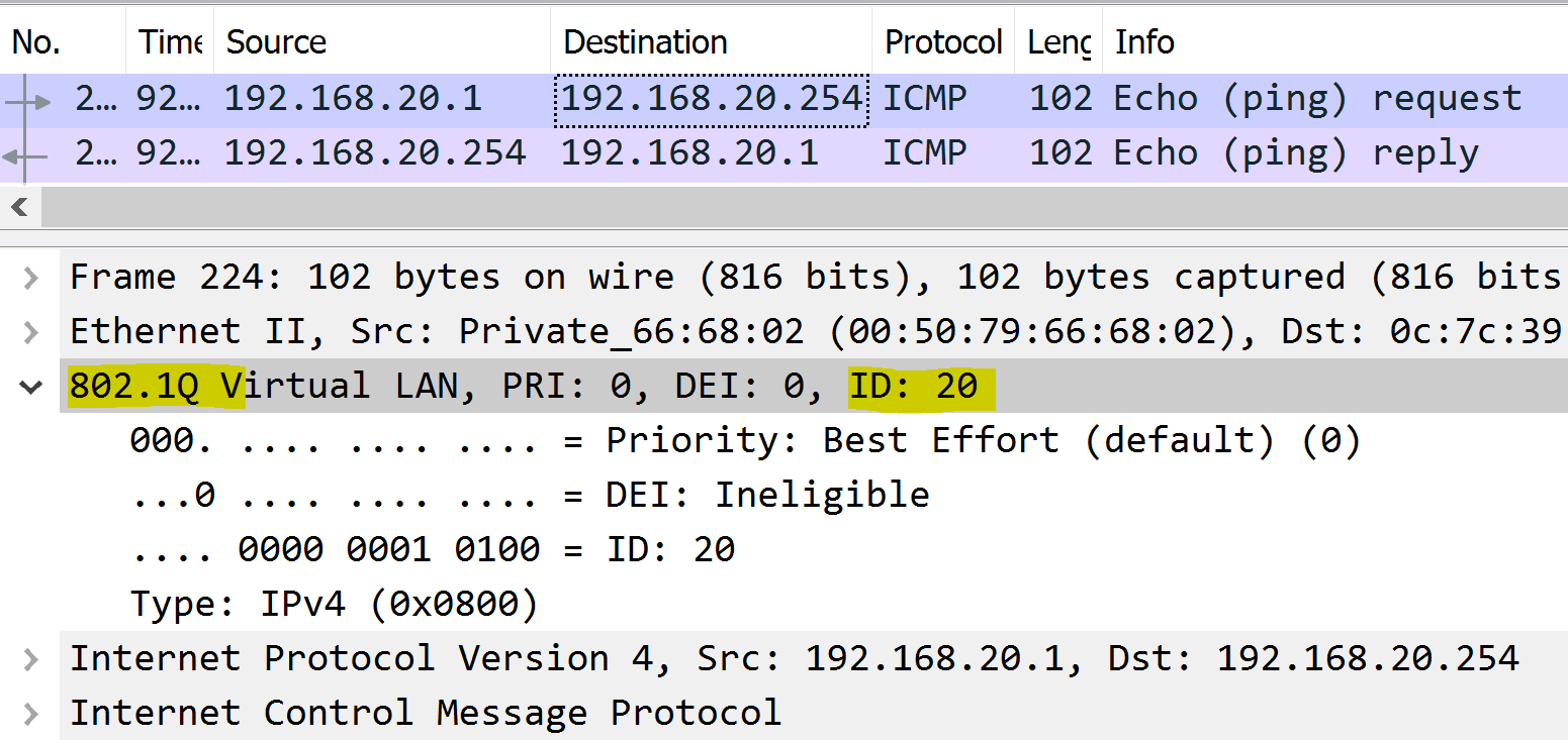
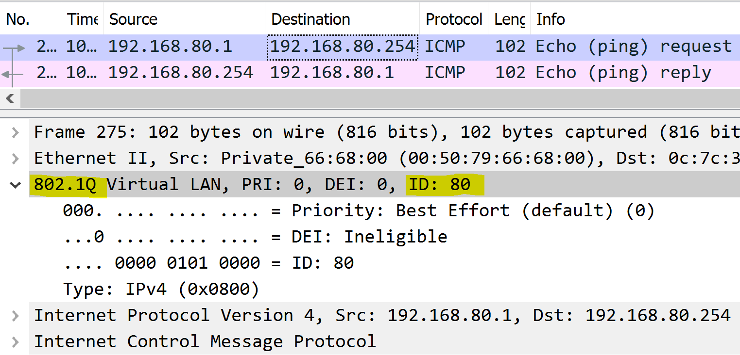
Each packet is tagged with a 802.1Q header tag with the originating source VLAN.
VLAN 10 - Engineering to Gateway
VLAN 20 - Finance to Gateway
VLAN 60 - MGMT to Gateway

VLAN 80 - Servers to Gateway
(SVIs) Inter-VLAN Routing Configuration
Scenario:
- In this lab scenario, I will configure Layer 3 switch Inter-VLAN routing using SVIs
- I will configure four SVIs on the Core switch for each VLAN
- I will configure a routed port on Core switch's Gi1/0 interface towards Gateway-R1 router for any outbound Internet traffic that is generated by hosts in each VLAN
- I will configure static routes on the Core Switch and Router to allow for reachability between networks
- I will configure Interface NAT on the virtual router to allow the my ISP device upstream to communicate with the bridged GNS3 VLAN networks
- I will test Internet connectivity on each VLAN PC
- I will analyze a packet capture on Core's Gi1/0 interface and the Gi0/0 interface of the Router for outbound Internet traffic
- Down stream trunk links have already been configured on the Core switch

HQ-Core-SW1
Configure SVIs & assign IP addresses & enable layer 3 routing.
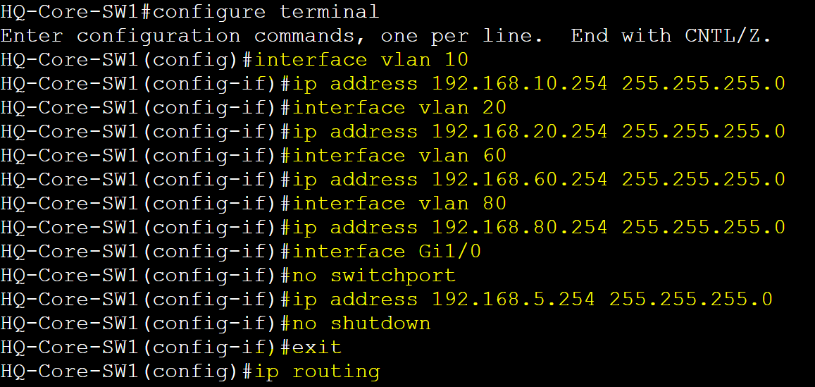
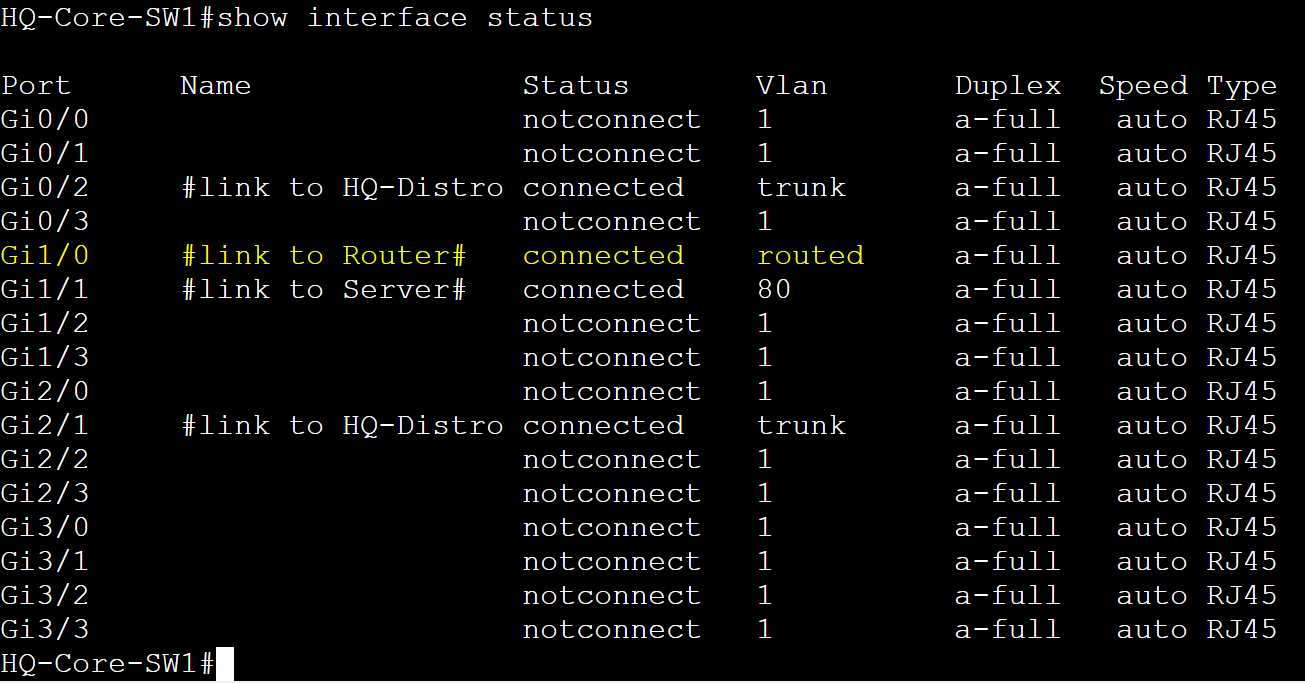
Confirm all SVIs and routed port are in an up/up state.

Confirm port Gi1/0 is a layer 3 routed port.
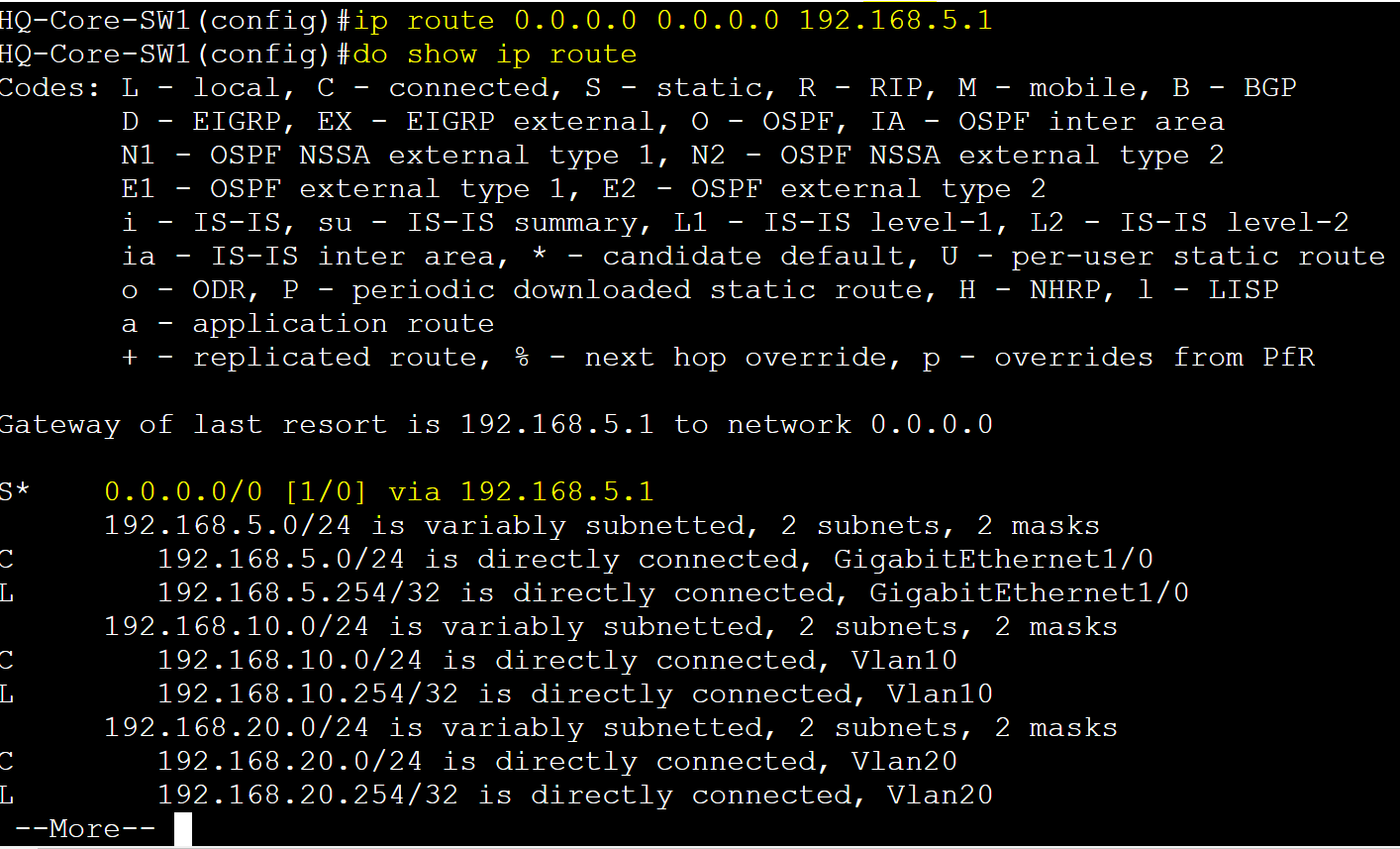
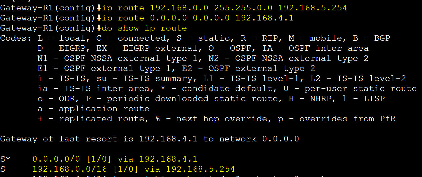
Add a default route towards the gateway router performing NAT.
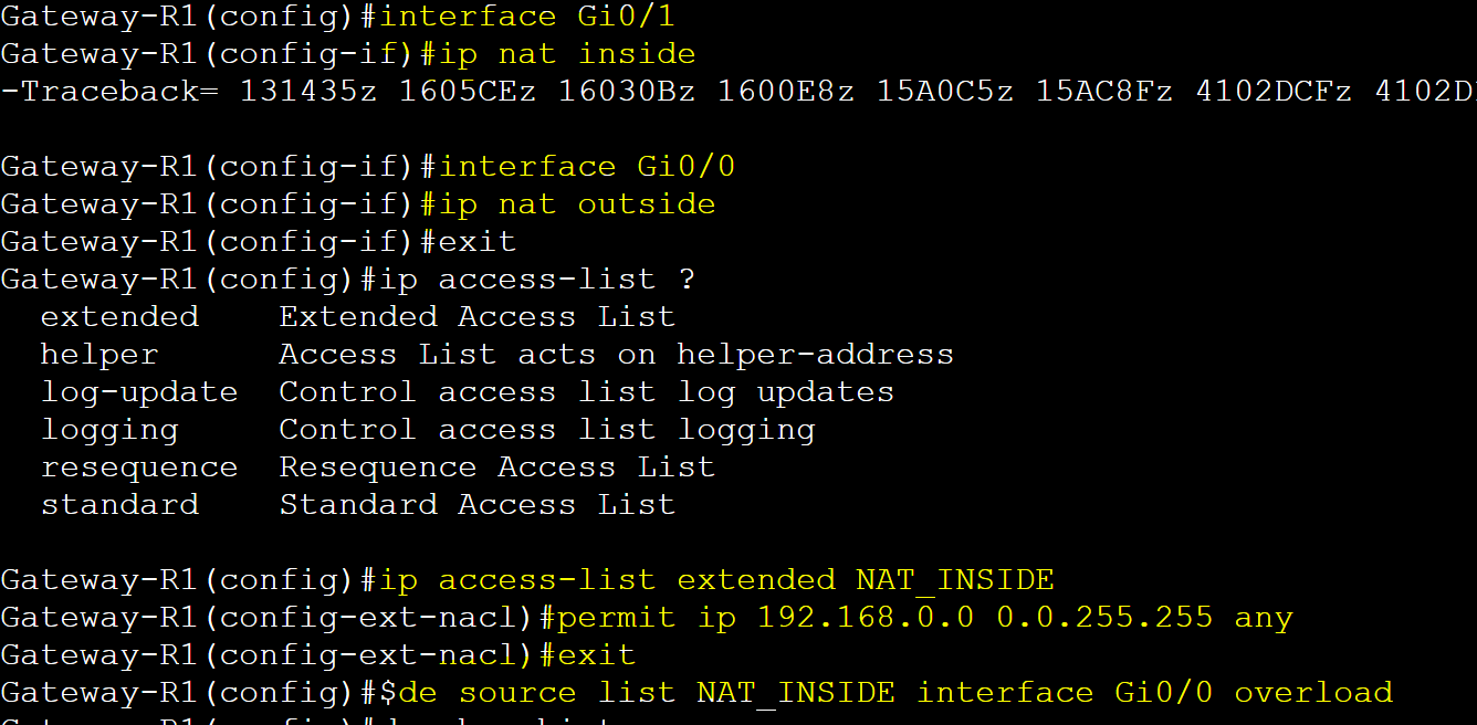
Gateway-R1
IP address configurations.

NAT (PAT) configuration.
Adding default route towards Internet & return route towards the VLAN subnets.
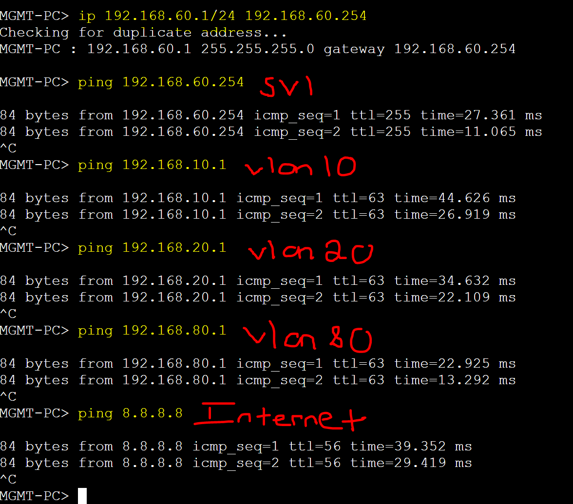
PC Ping Tests to Gateways
VLAN 80 (Servers)
Perform ping tests to the SVI gateway, PCs in different VLANs, & Internet.

VLAN 10 (Engineering)
Perform ping tests to the SVI gateway, PCs in different VLANs, & Internet.

VLAN 20 (Finance)
Perform ping tests to the SVI gateway, PCs in different VLANs, & Internet.

VLAN 60 (MGMT)
Perform ping tests to the SVI gateway, PCs in different VLANs, & Internet.
Packet Captures
Gi1/0 Routed Port - Core Switch to Router (Pre-NAT)

Gi0/0 Router Port - Router to Internet (Post-NAT - all traffic sourced from router)
