Overview
Sections:
- Data-Link & Broadcast Domains
- ARP Overview
- ARP Packet Captures
- Updated MAC & ARP Tables
- Problems with Broadcast Domains
Overview:
- The purpose of VLANs or Virtual Local Area Networks, is to logically segment and break down a larger physical network into multiple broadcast domains to improve network performance, security, and manageability
Use Case Scenarios:
- Traffic Segmentation
- Dividing a network into smaller subnets reduces unnecessary broadcast traffic
- Improved Security
- Limits the access to each other's data as devices are isolated into separate VLANs
- Simplified Network Management
- Grouping devices in a VLAN allows us to apply specific security policies such as QoS, firewall rules, or ACLs tailored to the needs of each VLAN
- Scalability
- Devices can be added to a pre-existing VLAN as the network grows
Data Link & Broadcast Domains
To better understand VLANs, let's take a deep dive into the following OSI Layer 2 Data Link concepts in a GNS3 lab.
- ARP
- Broadcast Domains
- MAC Address Tables
Layer 2 switches operate at the Data Link layer of the OSI model and utilize/build a MAC address table, also known as a forwarding table that map MAC addresses to specific ports.
When a switch receives a frame on one of its ports, it learns the source MAC address of the device that sent the frame and associates this MAC address with the port it arrived on.
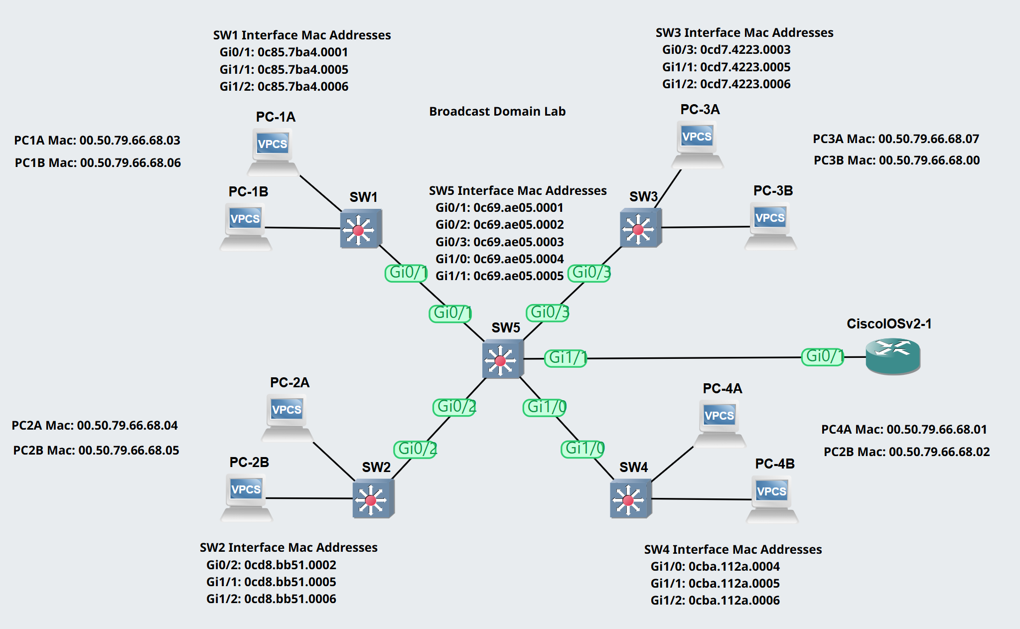
Scenario: SW1
In this scenario lets analyze SW1's current Mac address table and have PC-1A send traffic towards PC-4B in which we will then analyze SW1's Mac address table once more.
By default, all layer 2 switches will dynamically learn MAC addresses of all other switches that are located in the same Broadcast domain or network/subnet
- This dynamic nature is due to a switch seeing another switch connected to one of its ports and the internal data flows between switches in the domain
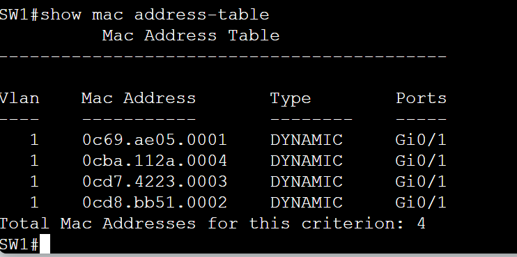
Analyzing Sw1's MAC address table, SW1 has dynamically learned the interface MAC address of SW2, SW3, SW4, and SW5.
As clients on the network begin sending traffic, demonstrated shortly, switches will begin mapping their MAC addresses with the port the frame was received on.
ARP Overview
ARP Overview
- ARP or the Address Resolution Protocol, is a layer 2 protocol that is used to map a network layer IP address to a data link layer MAC address when only the IP address is known
- ARP is essential for devices like PCs on the same network to communicate with each other using the correct physical MAC addresses
- The ARP process happens on the host device (not the switch), and once the MAC address is resolved, the switch then learns and stores the MAC address in the table for future forwarding decisions
- To summarize, network devices communicate using MAC addresses at the data link layer and IP addresses at the network layer which are all encapsulated in a data packet
How it Works
- When a device like a PC wants to send data to another device on the same network, it must know the MAC address associated with the recipient's IP address
- The sending PC broadcasts an ARP request message to all devices on the network theoretically asking, "Who has IP address X.X.X.X? Tell me your MAC address."
- The device that has the requested IP address responds with its MAC address
- The requesting device then stores this MAC address in its ARP cache for future use
- The ARP cache is a temporary table per device that stores recently mapped IP to MAC pairs
- Note:
- If a PC's ARP cache is cleared purposely, switches will facilitate re-broadcasting an ARP request message on behalf of the host even if there is still a MAC address entry of the destination device in the MAC Address table
- To summarize, switches are only aware of MAC addresses and not IP addresses
Types of ARP
- ARP Request
- Broadcast message sent to ask for the MAC address associated with an IP address
- The unknown destination MAC address of a broadcast message is noted with an address of ff:ff:ff:ff:ff:ff
- ARP Reply
- The response sent from the device with the requested MAC address
ARP Packet Captures
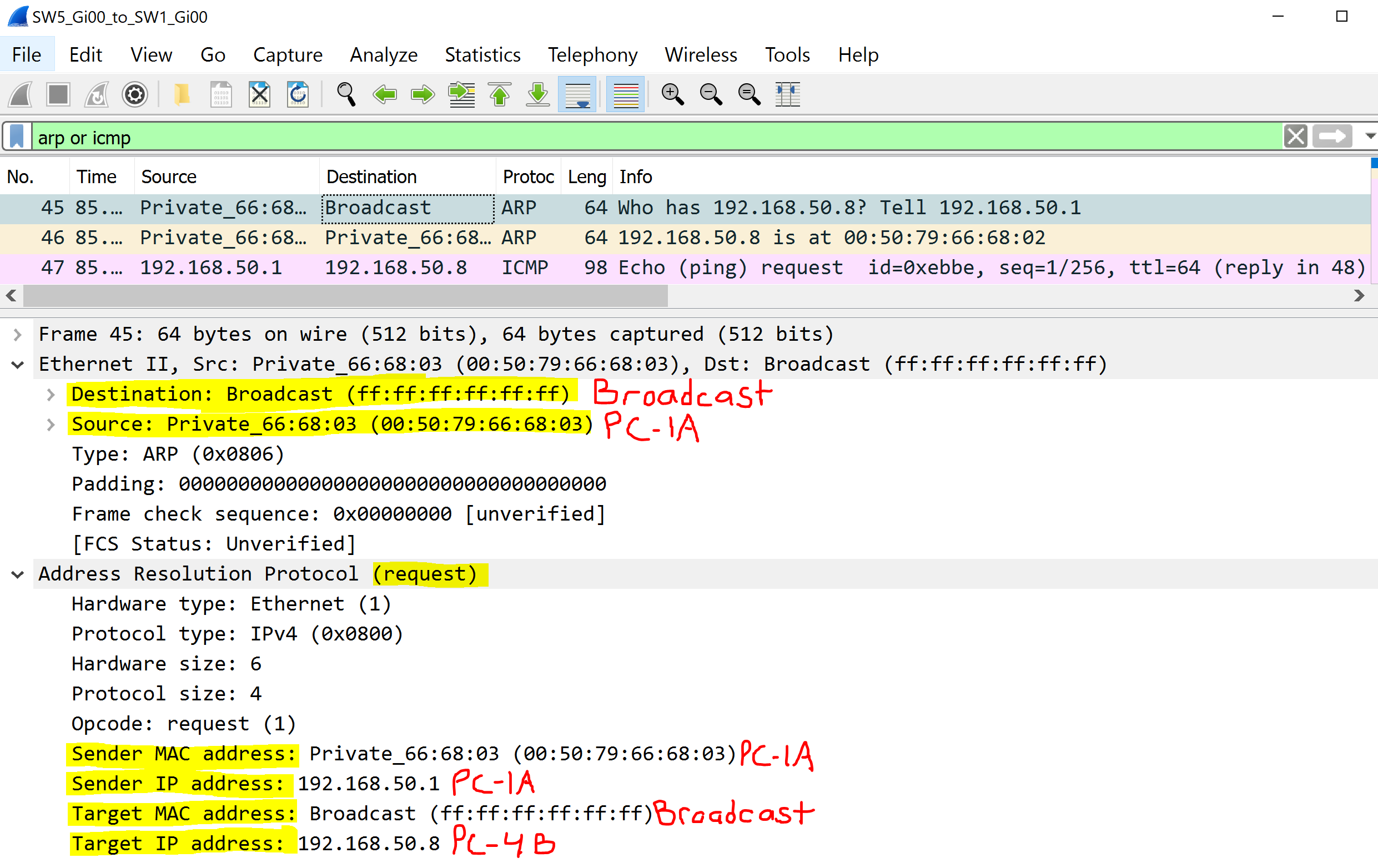
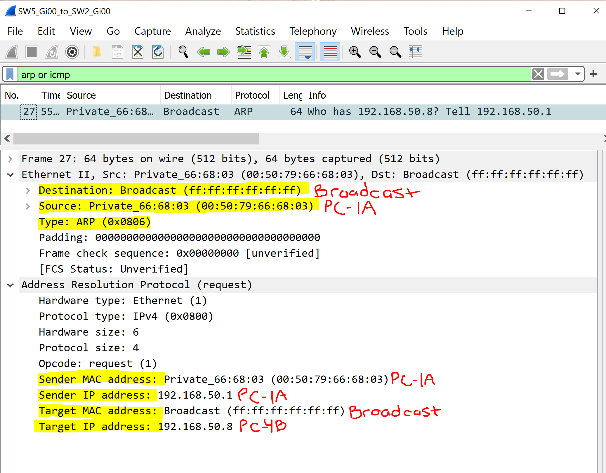
ARP Request
PC-1A sends out a broadcast ARP request towards SW1.
SW1 takes this ARP request packet and broadcasts out of all ports except the port the ARP request was received on.
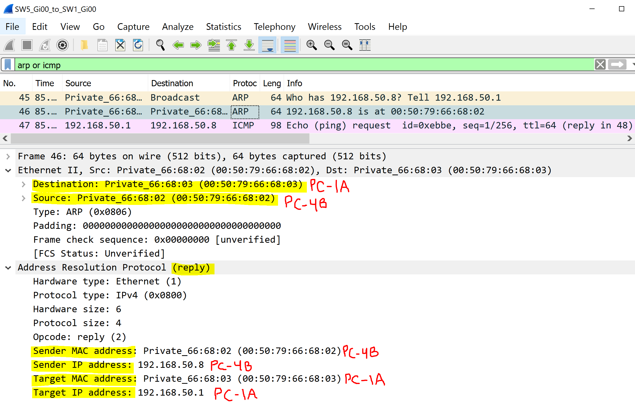
ARP Reply
PC-4B responds to the ARP Request with its MAC address in a ARP reply packet.
At this point, all switches know the MAC address of PC-1A due to the results of the initial ARP Request broadcast message and will know which port to send the ARP Reply packet to reach PC-1A.
The ARP Reply is a unicast message and does not need to be broadcast out of all ports as the switches in the direct path have a MAC address entry of both the sender and receiver host.
Broadcast ARP Request Dropped
In this scenario during the initial ARP request from PC-1A, switches 2 and 3 broadcast the ARP Request to the PCs off those switches.
No ARP replies are produced as the PCs off those switches silently drop the ARP Request packet because the destination IP of 192.168.50.8 in the packet does not match with their configured IP address.
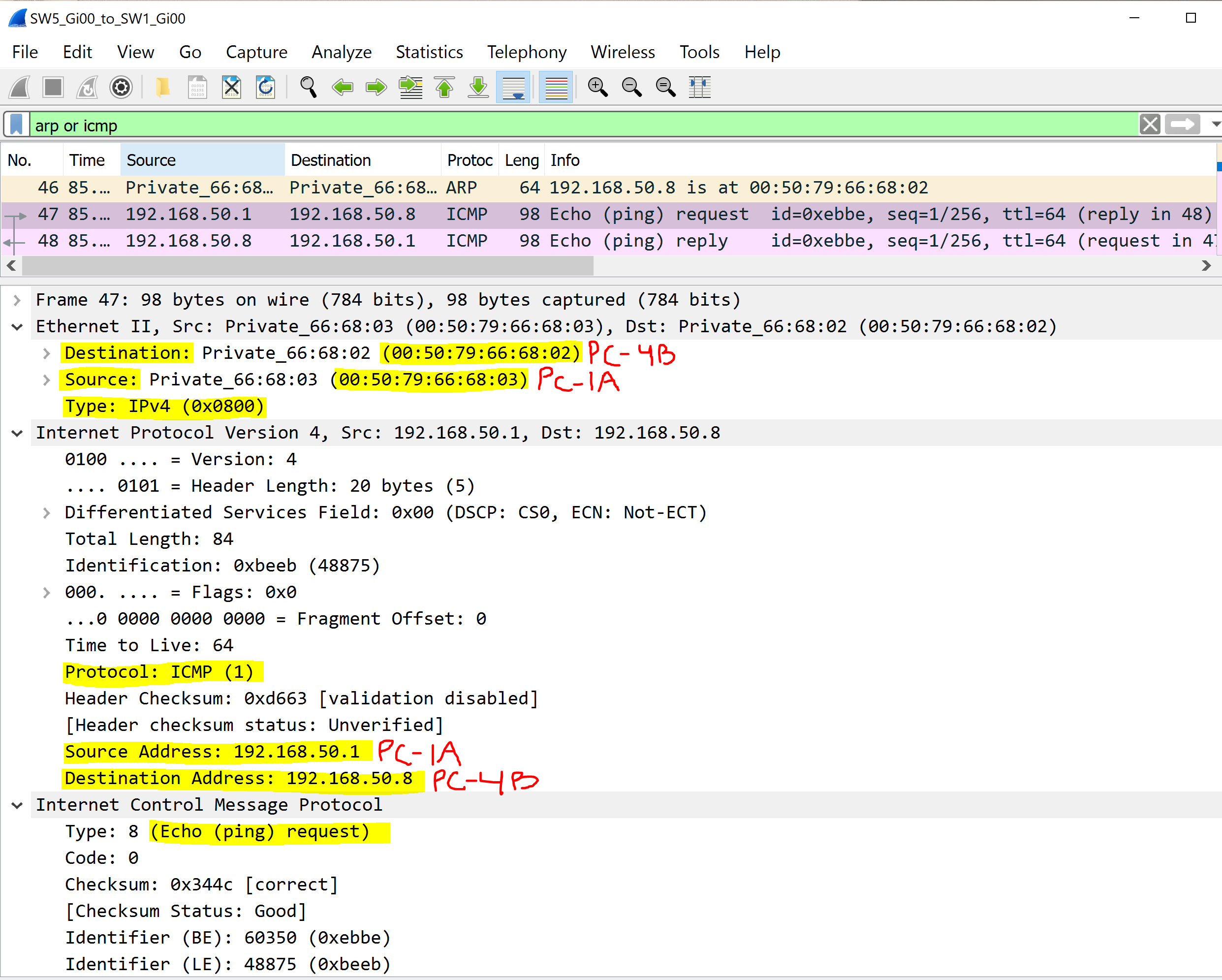
ICMP Request
After the ARP process has been completed, PC-1A is now able to send a ping request packet towards PC-4B as it now knows the Mac Address of PC-4B located in its ARP cache.
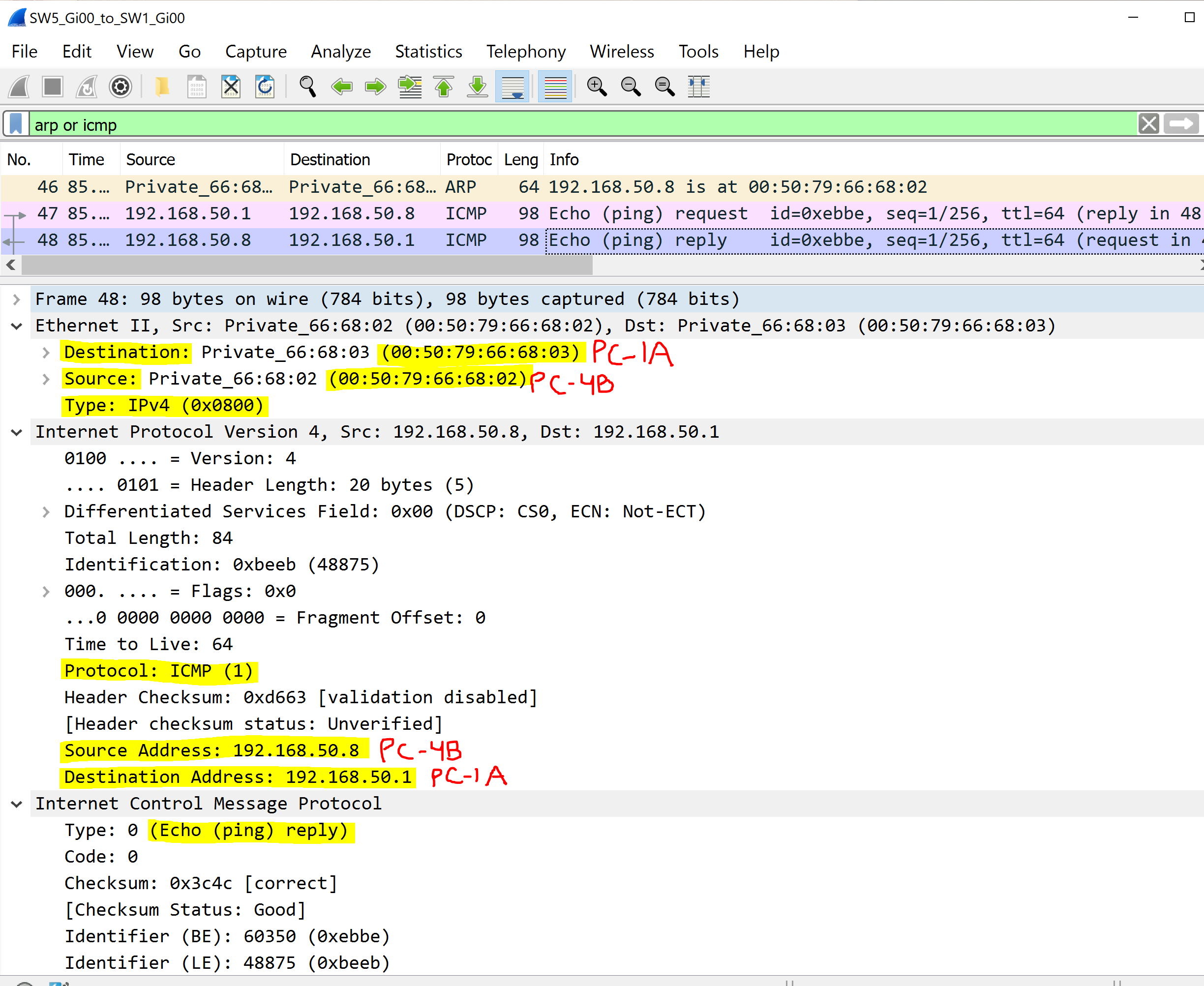
ICMP Reply
PC-4B receives the ICMP ping request packet and responds with a ICMP ping reply packet towards the sender PC-1A.
Updated MAC & ARP Tables
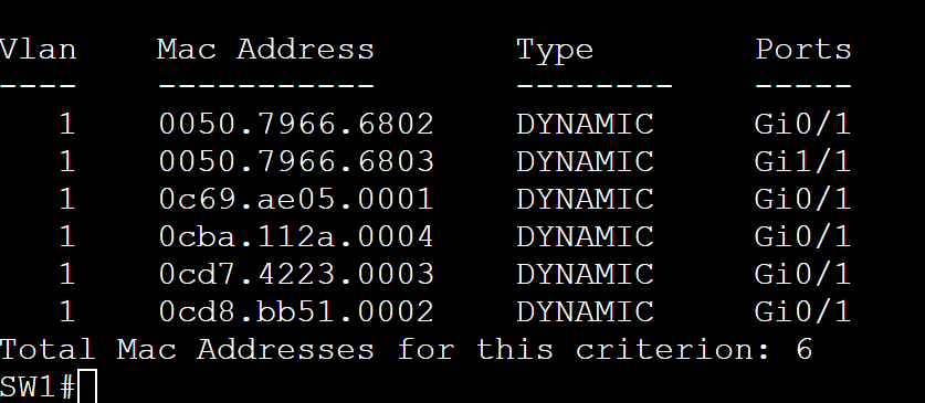
SW1 Updated MAC Address Table
After the completed ARP and ping process, SW1 has learned PC-1A and PC-4B's MAC address and have been learned dynamically and stored in the MAC address table.
- PC-4B MAC Address: 00.50.79.66.68.02 off of port Gi0/1
- PC-1A MAC Address: 00.50.79.66.68.03 off of Gi1/1
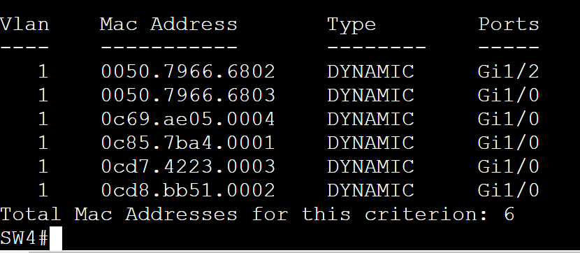
SW4 Updated MAC Address Table
SW4 learned the following:
- PC-1A MAC Address: 00.50.79.66.68.03 off of port Gi1/0
- PC-4B MAC Address: 00.50.79.66.68.02 off of port Gi1/2
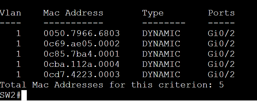
SW2 Updated MAC Address Table
SW2 only learned the MAC Address of PC-1A from the initial ARP Request Broadcast message.
The ARP Reply was a unicast packet from SW4 to SW5 then to SW1 and did not need to pass SW2 to learn PC-4Bs MAC address.
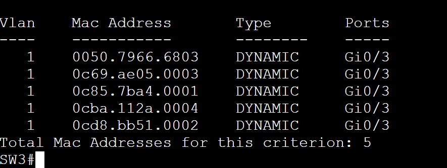
SW3 Updated MAC Address Table
Much like SW2s scenario, SW3 only learned the MAC Address of PC-1A from the initial ARP Request Broadcast message.
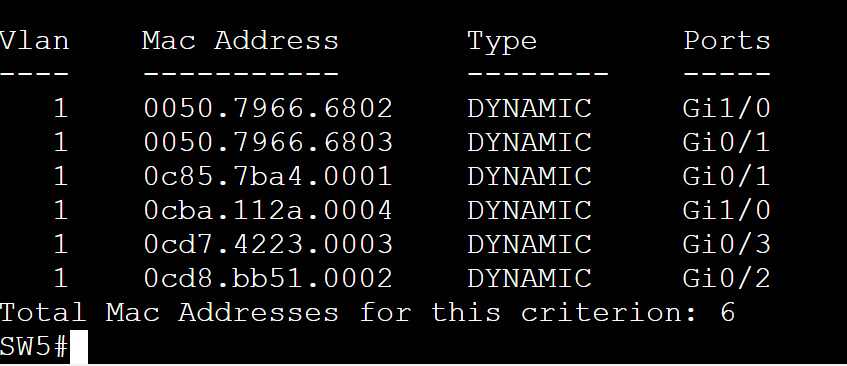
SW5 Updated MAC Address Table
SW5 learned both PC-1As and PC-4Bs MAC address as the unicast ARP reply had to pass through SW5 consisting the source MAC address of PC-4B in the ARP reply.
Updated ARP Tables
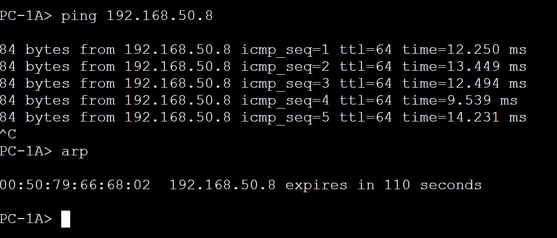
PC-1A Updated ARP Table
After the completion of the ARP request and reply procedure, PC-1A has stored the IP address to MAC address binding entry of PC-4B.
PC-4B Updated ARP Table
After the completion of the ARP request and reply procedure, PC-4B has stored the IP address to MAC address binding entry of PC-1A.

Problems with Broadcast Domains
As the network grows larger, so do the broadcast domains and can therefore cause concerns on the network.
In a broadcast domain, a broadcast frame is received by every device, regardless of whether the device needs the frame or not causing the following:
- Decreased Network Performance
- Large amounts of broadcast traffic will have to be processed by devices that don't need it decreasing performance
- Security Risks
- In a large broadcast domain, sensitive data can be unintentionally exposed by unwanted broadcasts increasing the risk of the data being intercepted
- Difficultly in Troubleshooting
- When a network grows larger it can become a challenge to isolate issues
VLANs can assist in alleviating these concerns by breaking down and segmenting a single broadcast domain or network into smaller subnetworks and broadcast domains which will be beneficial as the network grows.