Global Settings & Upgrades
Sections:
- Lab Topology
- Management VLAN
- Spanning Tree
- Quality of Service (QoS)
- Multicast
- Maximum Transmission Unit (MTU)
- Power Supply Settings
- Network Client Sampling
- Staged Upgrades
Resources:
- Switch Settings
- Configuring Spanning Tree on MS Switches
- QoS (Quality of Service)
- MS Switch QoS Defined
- Multicast Overview
- Troubleshooting MTU Issues
- Combined Power on MS Switches
- Network Client Sampling
- MS Firmware Upgrades
Overview:
- The switch settings refer to a set of configurable options and features that control the behavior of the switch and how it interacts with the network. These global settings are available within the Meraki Dashboard
- In this section, I will demonstrate the available global options offered and configurable via the Meraki Dashboard
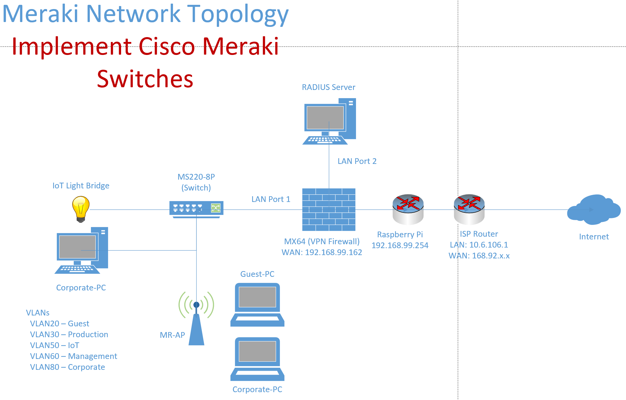
Lab Topology
Management VLAN
Overview:
- The Management VLAN refers to the VLAN that is used to manage the switch and other network devices
- The Management VLAN is critical because it isolates management traffic from user or application traffic, enhancing security and ensuring that network management operations are not disrupted by regular network activity
- Per Cisco, the switch will try to contact the Meraki Dashboard on the untagged (native) VLAN 1 by default
- It's important to note that assigning a static IP and/or VLAN to a switch will override management VLAN settings configured in this section
- In this section, I will demonstrate configuring the management VLAN on my lab Meraki MS switch
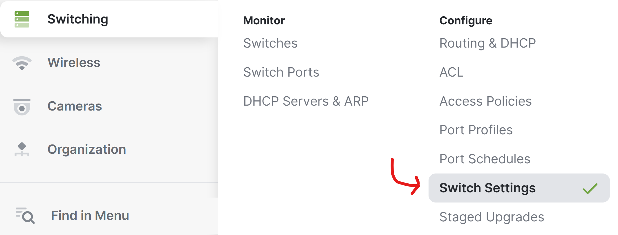
Switch Settings Menu
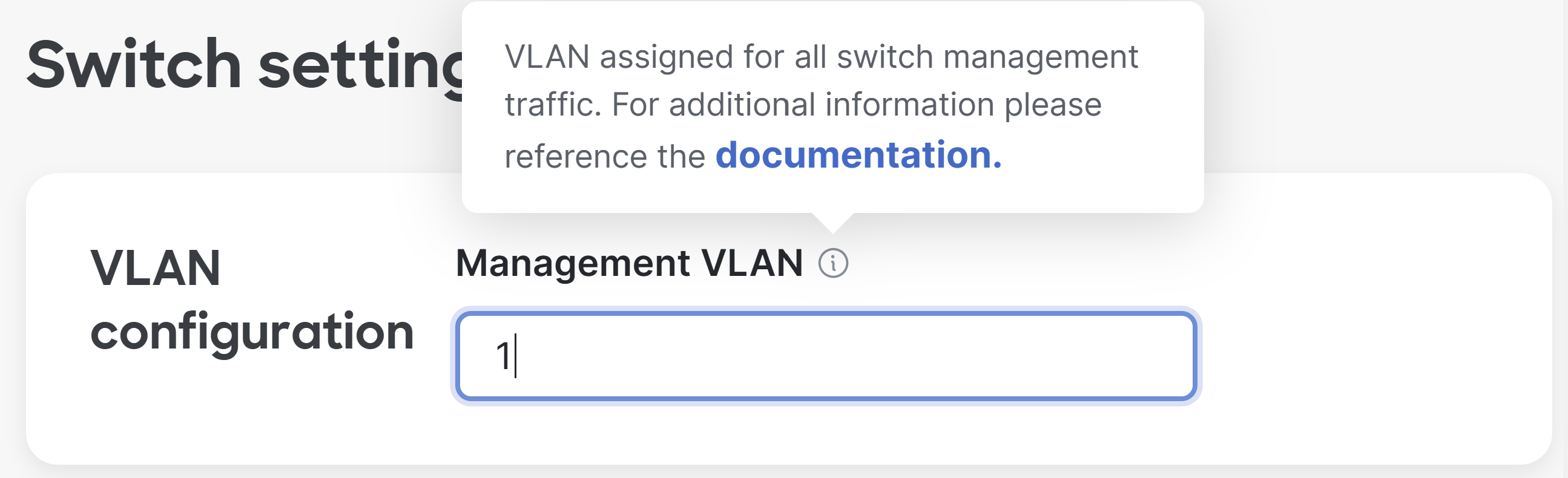
Default Management VLAN
Management VLAN Configuration
Overview:
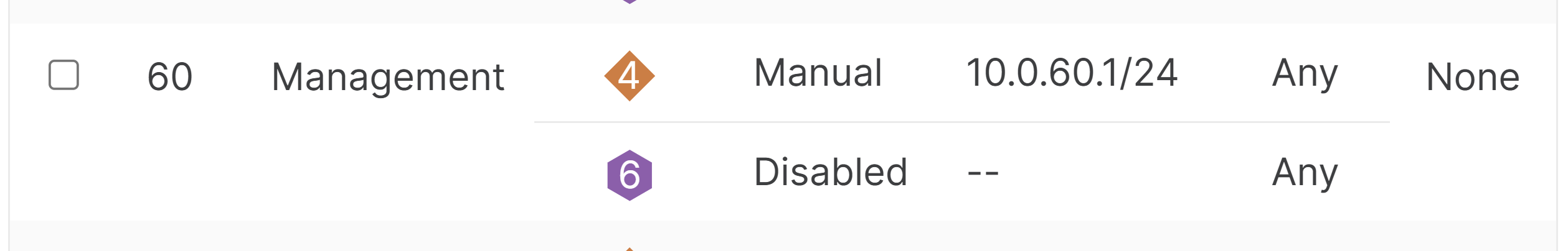
- In this lab environment example, I have defined a dedicated Management VLAN on my Meraki MX Security Appliance
- With the Management VLAN concept, there are two ways to set the Management VLAN on a Meraki switch
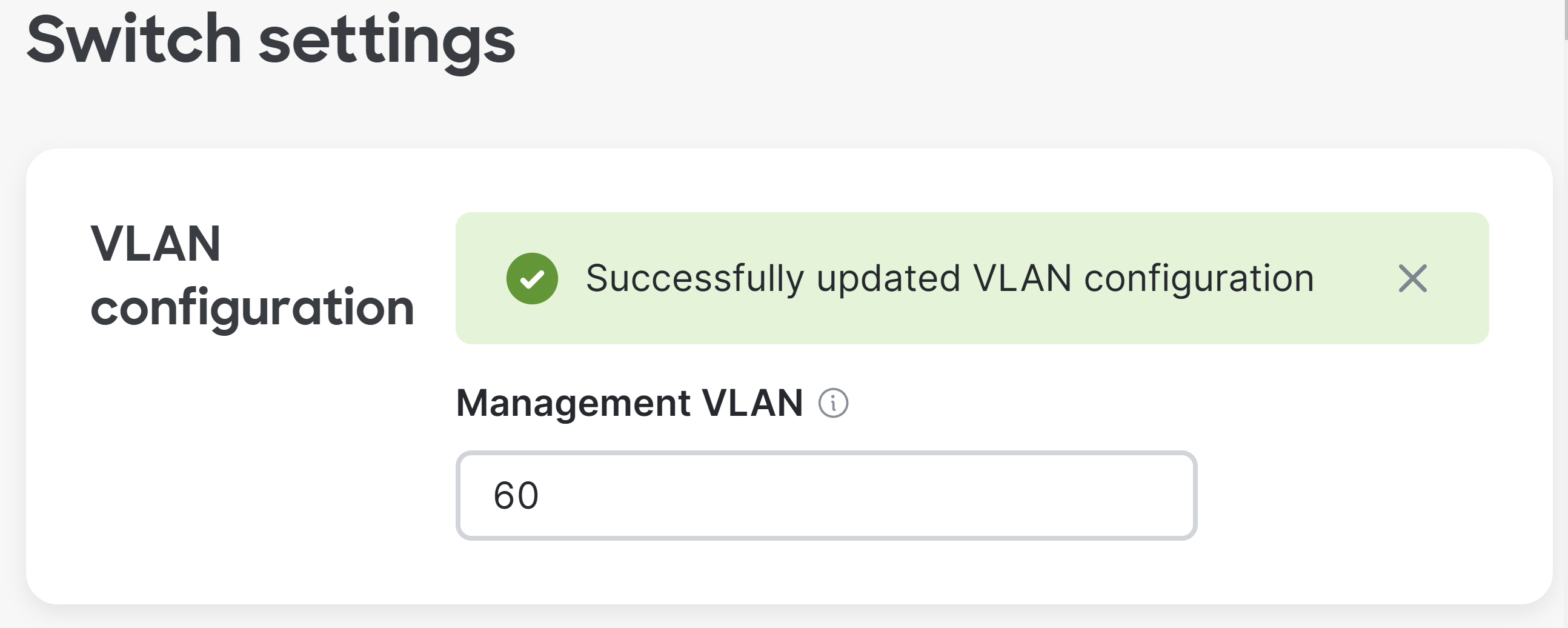
- First way is to set the Management VLAN from the Switch Settings as illustrated below
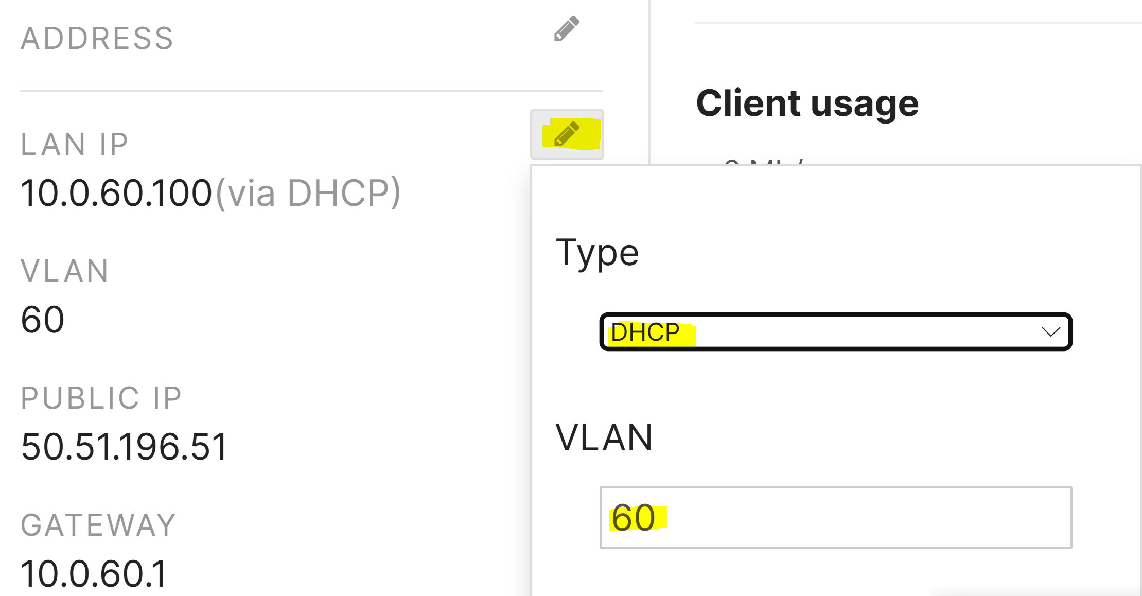
- Second way is to manually assign a management VLAN by setting the IP address of the switch under 'Monitor >> Switches'
Dedicated Management VLAN Defined on MX Appliance
Method 1: Defining Management VLAN in Global Switch Settings
Method 2: Defining Management VLAN in Monitor >> Switches

Spanning Tree (STP)
Overview
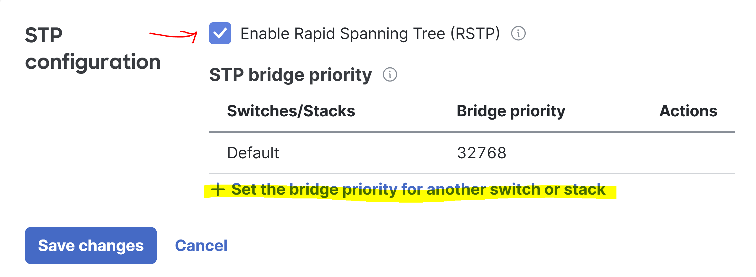
- The STP Global Configuration settings allow you to configure the RSTP 802.1w or STP 802.1D standards of Spanning Tree and the bridge priority value of switches in the network
- The default bridge priority for all Meraki switches is '32768' and is recommended that you set the priority of your desired root bridge to '4096' to ensure its election
- Per Cisco, it is best practice to set a layered approach to the STP priorities in a network. For instance, if there is a clear Core <> Distribution <> Access Layer, priorities should be Core (4096), Distribution (16384), and Access (61440)
- In my lab scenario, as I'm only utilizing a single switch in my topology, it is considering itself as a Root Bridge even with the default priority value of '32768'
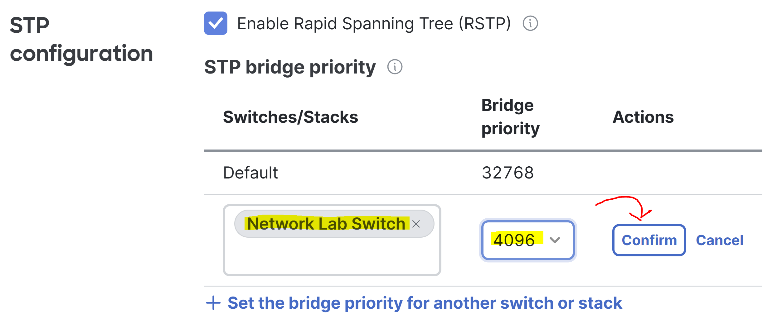
- I will modify the default STP priority value to '4096' to demonstrate the setting
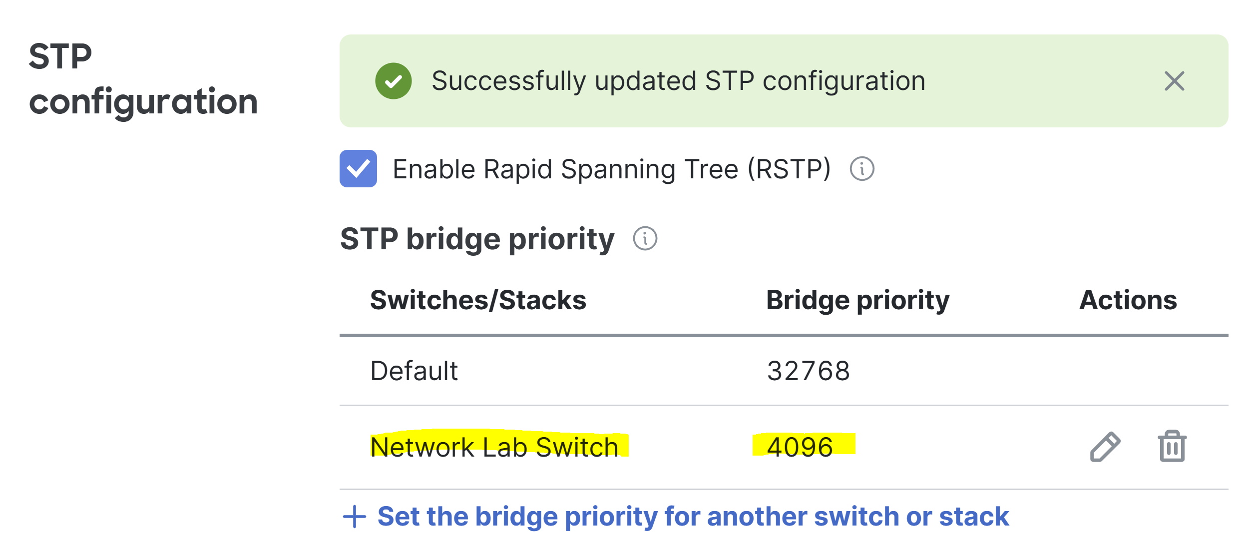
STP Configuration
Overview
- By default, any switch prirorities that have not been manually modified will default to the priority value of '32768'
- I have manually assigned my Meraki lab switch a priority value of '4096' to ensure it remains the root bridge if other switches join my network
- RSTP is an improved open standard of Spanning Tree and should be utilized and preferred over the original STP 802.1D standard
Quality of Service (QoS)
Overview:
- QoS or Quality of Service refers to a set of technologies and features that prioritize traffic to ensure that high priority applications like VoIP or video conferencing receive the necessary bandwidth they require
- Per Cisco, configuring QoS on your Meraki switches is done at the Network level which means it automatically applies to all of the switches in the Meraki Network
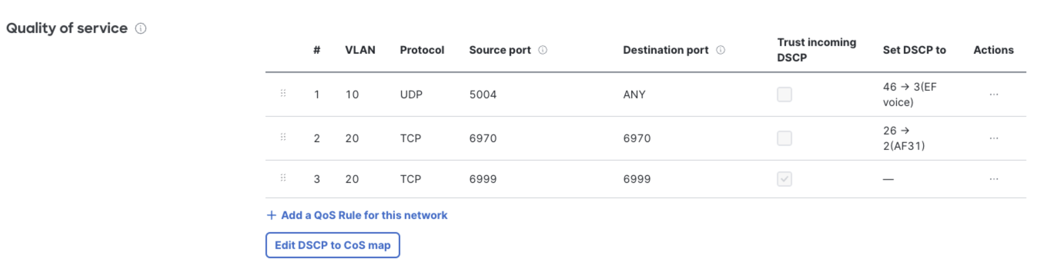
- In the QoS section, rules can be defined along with DSCP tags, protocols, and source and destination ports
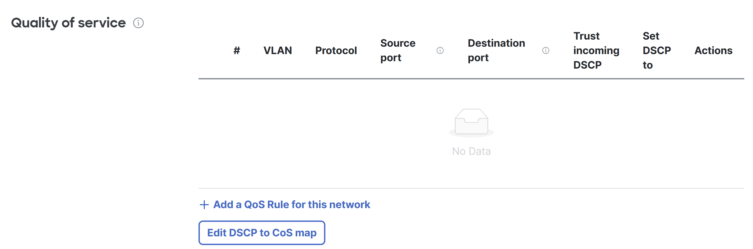
QoS Configuration Overview
Cisco (VoIP & Video) Configuration Example
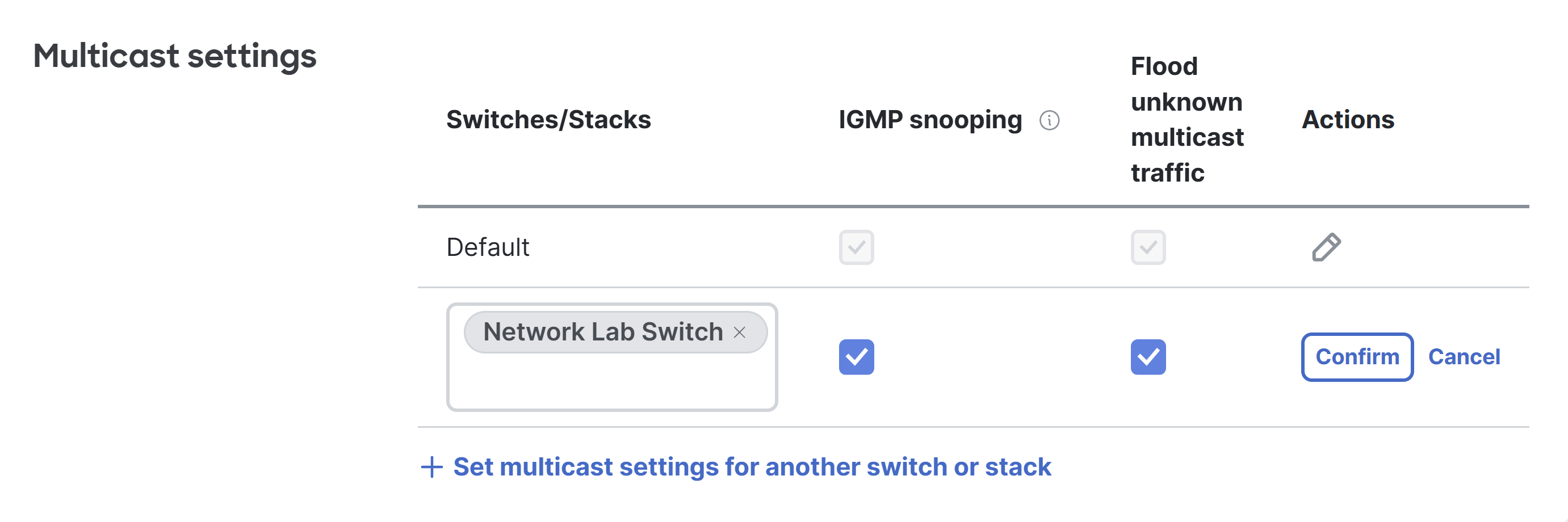
Multicast Settings
Overview:
- Multicast is a method of sending network traffic to multiple devices at once, rather than broadcasting it to all devices (broadcast) or sending it individually to each device via unicast
- This feature is commonly used for applications such as video streaming, online gaming, and real time communications like video conferencing
- With the multicast global switch settings, IGMP Snooping can be configured on a per switch basis. IGMP Snooping is used by switches to monitor and manage multicast group memberships on the network. It helps switches understand which clients are part of specific multicast groups
MTU Configuration
Overview:
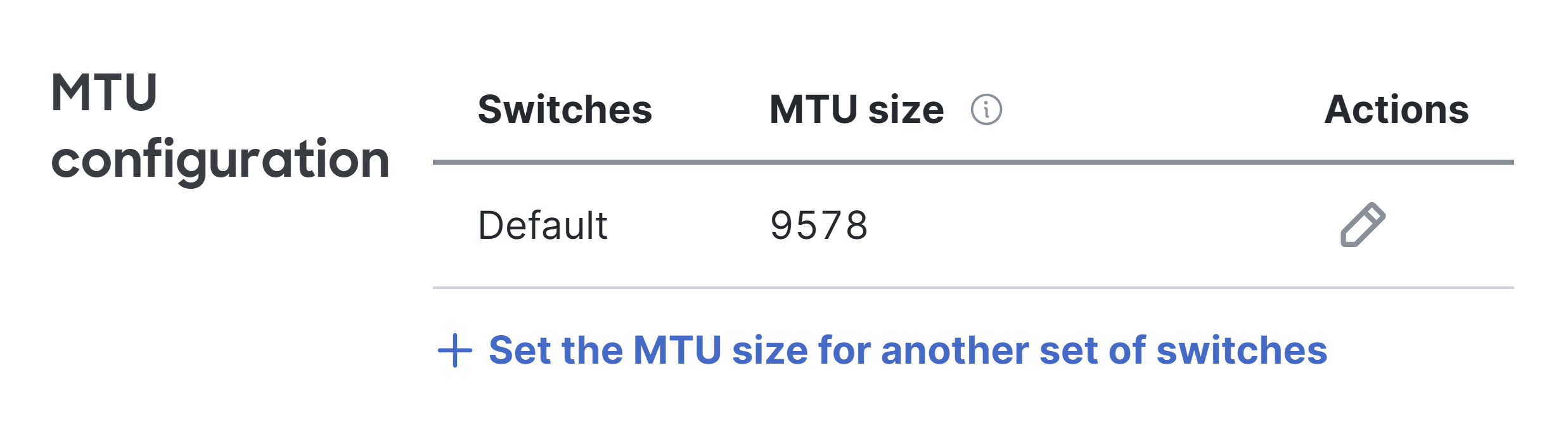
- MTU or the Maximum Transmission Unit refers to the largest size of a data packet (bytes) that can be transmitted over the network without fragmentation
- The MTU setting is an important factor in optimizing network performance and ensuring the smooth transmission of data across the network
- Higher MTU values allow more data to be sent in a single packet, reducing the overhead from headers and increasing overall throughput of the network
- While increasing the MTU can boost performance, its important to ensure that all devices in the network can handle the larger MTU, as devices that are not capable of supporting it may drop or fragment packets
MTU Configuration Overview
Power Supply Settings
Overview
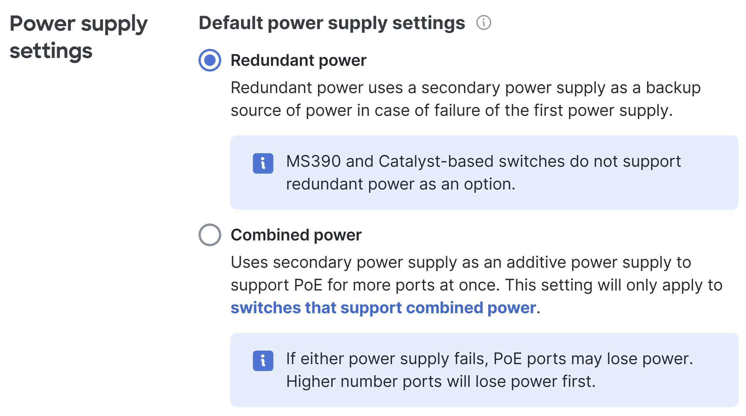
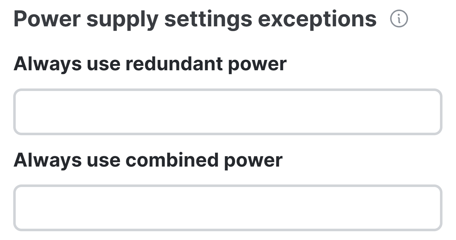
- The Power Supply Redundant and Combined Power settings relate to the configuration and management of the switch's power supplies, specifically switches that have dual power supplies
- These settings ensure that the switch can maintain power availability even if one of the power supplies fail, or allow for power to be distributed more effectively when using multiple power supplies
Power Supply Overview
Network Client Sampling
Overview
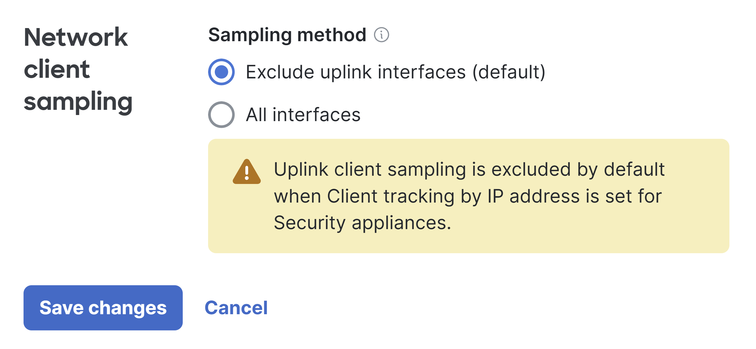
- Network Client Sampling refers to the process of capturing and monitoring a sample of network traffic to analyze the behavior and performance of client devices on the network
- The primary purpose of Client Sampling is to gather insights into network performance, traffic patterns, and device activity without needing to continuously monitor all traffic across the network
- This helps in making informed decisions about network optimization and troubleshooting without causing an excessive burden on resources
Network Client Sampling Overview
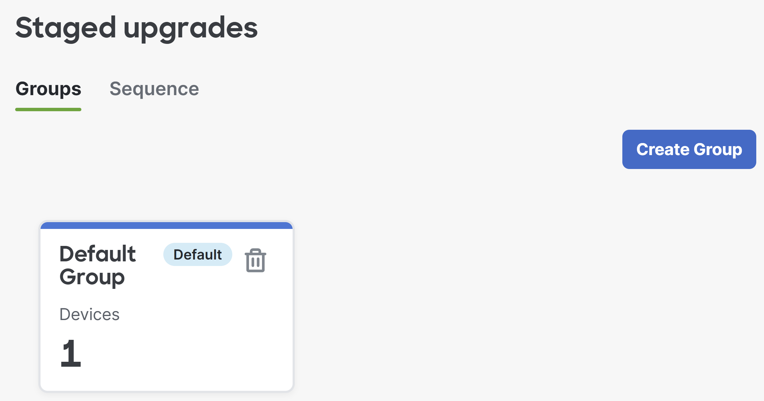
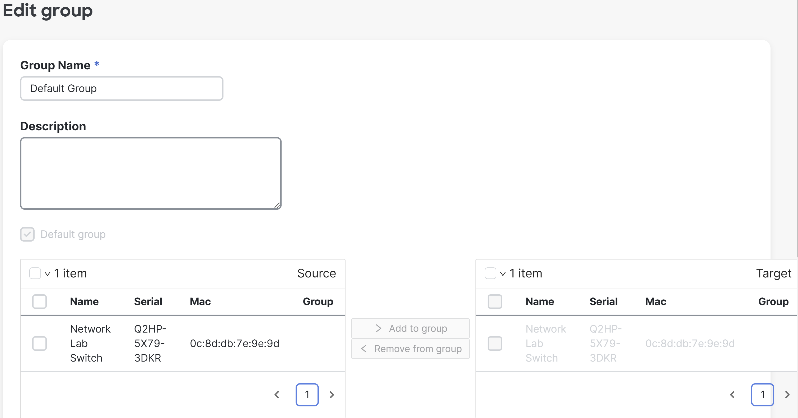
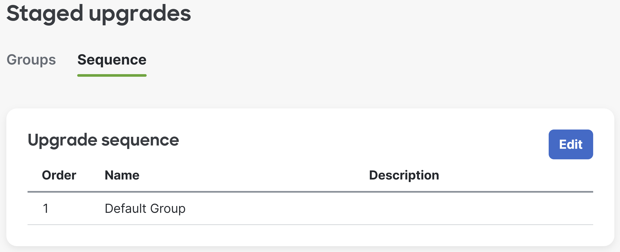
Staged Upgrades
Overview
- Per Cisco, staged upgrades allows admins to divide a network of switches into smaller groups which can have firmware upgraded at separate times
- With staged upgrades, admins can schedule, defer, and rollback firmware upgrades in stages, allowing for more flexibility of the upgrade process
- Staged Upgrades Use Cases
- The network has too many switches to upgrade in a single maintenance window
- More frequent maintenance windows are available for some devices than others. It may be reasonable to upgrade access layer switches that connect end user devices each night, but core layer switches can be upgraded once a month
Staged Upgrades Overview