Routing & DHCP Overview
Sections:
Resources:
Overview:
- Cisco Meraki switches with layer 3 functionaility provide more advanced routing capabilities than standard layer 2 switches
- These layer 3 switches are designed to support routing between different VLANs, providing inter-VLAN routing and access to more advanced management features
- Per Cisco, in order to enable and configure layer 3 routing on MS switches, a layer 3 capable switch is required
- Meraki has a dedicated product line of layer 3 switches and can be viewed using their switch datasheets available on the Web
- In this section, I will compare the differences between Layer 2 and Layer 3 Switching
Layer 2 vs Layer 3 Switching
Traditional Layer 2 Switching:
OSI Model
- Traditional switching operates at layer 2 of the OSI model, where packets are sent to specific switch ports based on destination MAC addresses
- A Layer 2 switch receives data frames, looks at the MAC address in the frame, and forwards the frame to the appropriate port that corresponds to that MAC address
Broadcast Domains
- Within a layer 2 switch environment exists a broadcast domain. Any broadcast traffic on a switch will be forwarded out to all ports except for the port the broadcast packet arrived on
- Broadcasts are contained in the same layer 2 segment, as they do not traverse past a layer 3 boundary
Layer 2 Ethernet Frame
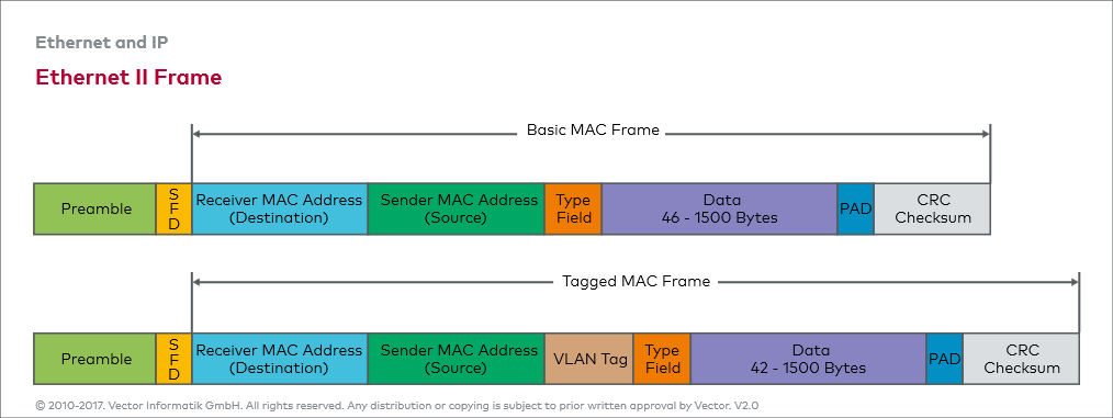
Ethernet Frame Fields
Preamble (7 bytes)
- The preamble in an Ethernet frame is a sequence of bits used to signal the start of the frame and synchronize communication between the sender and receiver
SFD (1 byte)
- The SFD or Start Frame Delimiter is a special byte that marks the end of the preamble and signals the start of the actual data portion of the Ethernet frame
Source MAC Address (6 byte)
- The 48 bit MAC address that helps the receiving device identify the sender
Destination MAC Address (6 byte)
- The 48 bit MAC address of the device that is intended to receive the frame
Type (2 byte)
- The Type field that indicates the protocol or the type of data encapsulated in the frame's payload such as IPv4/IPv6, ARP, etc
Data (46 - 1500 bytes)
- The Data field contains the actual data being transmitted between devices
- The maximum size of the data field is determined by the MTU which is usually 1500 bytes for Ethernet
Padding
- The Padding field is used if the payload or data field of the frame is smaller than 46 bytes. Padding is added to meet the minimum size requirement for an Ethernet frame (64 bytes total)
CRC (4 bytes)
- The purpose of the CRC or Cyclic Redundancy Check is to ensure that the data transmitted in the frame has not been corrupted during transmission
Layer 3 Switching:
OSI Model
- A Layer 3 switch operates at the Network layer (layer 3) of the OSI model. It deals with IP addresses and uses them to forward data packets between different networks or subnets
- Layer 2 MAC addresses use one big flat addressing scheme. There is no logical separation between networks at Layer 2, it's done at Layer 3
Layer 3 Switching
- A Layer 3 switch performs routing functions in addition to switching. It looks at the IP address in the packet and makes forwarding decisions based on IP routing tables. This allows it to route traffic between different networks
Layer 3 Packet Header
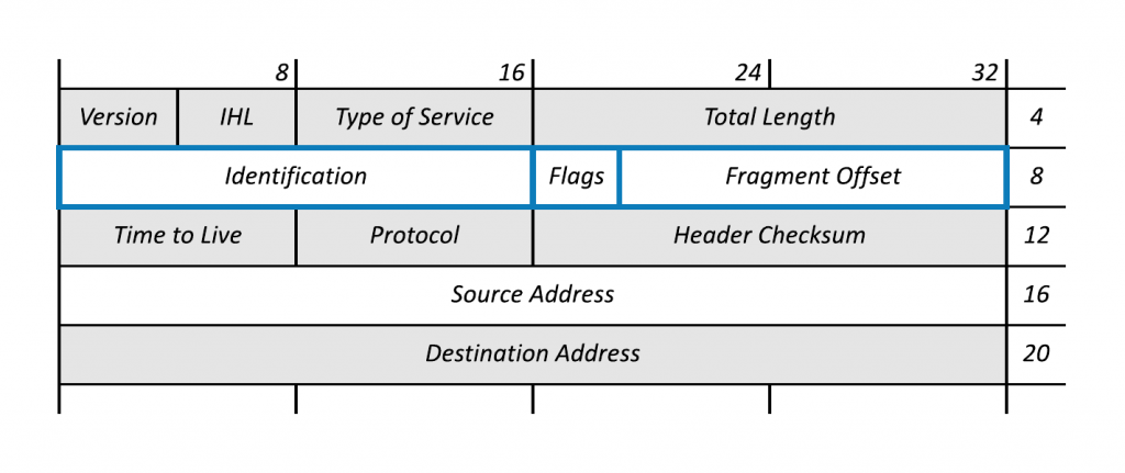
Packet Header Fields
Version (4-bit)
- The version field indicates the protocol version of the packet being transmitted: IPv4/IPv6
Internet Header Length (4-bit)
- The IHL field indicates the length of the IP header in 32-bit words (4-byte units)
Type of Service (8-bit)
- The ToS field specifies how the packet should be treated in terms of its priority and handling during transmission across the network
- This field is intended for QoS or Quality of Service helping layer 3 devices make decisions about how to prioritize traffic
Total Length (16-bit)
- The total length field specifies the total length of the IP packet including both the header and data varying from 0 - 65,535 bytes
Identification (16-bit)
- The identification field is used to uniquely identify each packet or fragment of a packet in a network
- When an IP packet is too large to be transmitted in a single unit, it is fragmented into smaller packets
- The Identification field helps to link those fragments together so they can be reassembled correctly by the receiver
Flags (3-bit)
- The flags field is used to control the fragmentation of the IP packet and determines whether a packet is fragmented, whether more fragments are expected, and how the packet should be handled during fragmentation
Fragment Offset (13-bit)
- The fragment offset field is used to indicate the position of a fragment in the original unfragmented packet and plays a critical role in reassembling fragmented packets once they reach their destination
Time to Live (8-bit)
- The TTL field plays an important role in controlling the lifetime of a packet in a network
- The TTL value helps prevent packets from circulating indefinitely if there is a routing loop or other issues in the network
- The TTL value specifies the number of hops the packets can pass through before being discarded
Protocol (8-bit)
- The protocol field indicates what type of higher layer protocol is being carried in the packet's payload
- The protocol field helps the receiving device understand how to interpret the data, directing it to the appropriate protocol handler
- Example protocols being (e.g., TCP, UDP, ICMP, OSPF)
Header Checksum (16-bit)
- The header checksum field is used for error detection to detect any changes or corruption that might occur in the header during transmission through the network
- When the packet reaches its destination or any other intermediate router, the receiver recalculates the checksum for the header and compares it with the value in the Header Checksum field
Source Address (32-bit)
- The 4byte address that specifies the IP address of the sender or source of the packet
Destination Address (32-bit)
- The 4byte address that specifies the IP address of the intended target or destination of the packet
Options (0 - 40 bytes)
- The options field provides a way for certain features or specific instructions to be added to the packet, such as routing controls or timestamps
- This field is typically used in special cases and is not always present in most data packets
Data (variable length)
- The data field refers to the part of the packet that carries the payload, the actual data being transmitted from the source to the destination
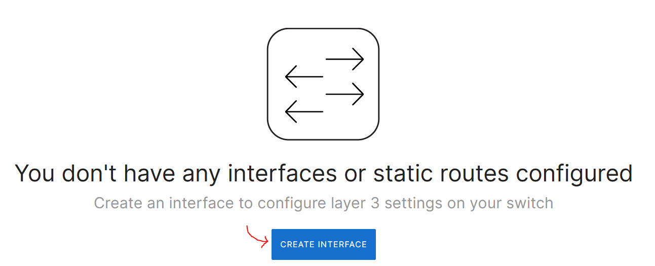
Layer 3 Switching Configuration Overview
Routing & DHCP Menu

Routing & DHCP Menu Overview: