SD-WAN & Traffic Shaping
Sections:
- Lab Topology
- SD-WAN Overview
- Traffic Shaping Overview
- Meraki's SD-WAN & Traffic Shaping Solution
- Secondary WAN Configuration
- SD-WAN Uplink Failover Configuration
- SD-WAN Flow Preferences Configuration
Resources:
Overview:
- SD-WAN and Traffic shaping on Meraki MX security appliances are two key features designed to improve network performance, optimize traffic, and provide better control over how bandwidth is utilized across the network
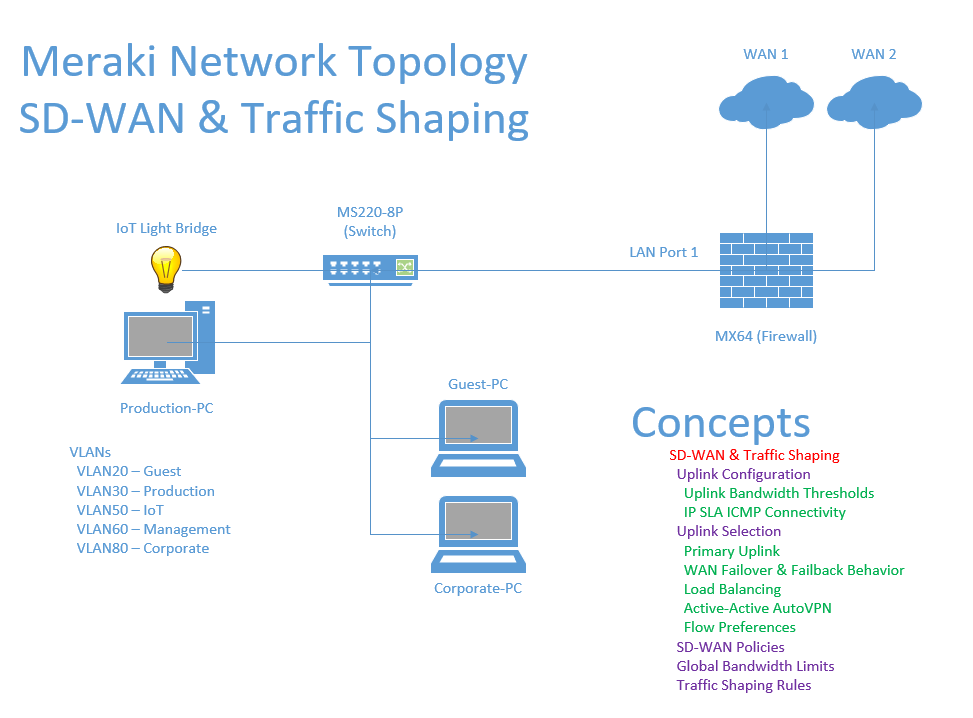
Lab Topology
SD-WAN Overview
SD-WAN Overview
- SD-WAN refers to a network architecture that uses software to manage wide area network traffic across multiple types of WAN circuit connections with the goal of optimizing performance and reducing costs
SD-WAN Benefits
- Redundant WAN Connections
- SD-WAN can use multiple WAN links (such as two ISPs) to ensure continuous network uptime
- Centralized Control
- SD-WAN offers centralized management through the Meraki Dashboard, allowing administrators to easily configure, monitor, and optimize WAN traffic
- Automatic Failover
- If one WAN link fails, SD-WAN can automatically failover to another link to maintain uptime
- Improved Application Performance
- SD-WAN can prioritize critical applications over less important traffic like file downloads
- Link Load Balancing Failover
- With Meraki's own SD-WAN solution, traffic can be distributed across multiple WAN links to balance load, and the MX appliance automatically switches to a backup link if the primary WAN link fails
- Real-Time Application Performance Monitoring
- The Meraki Dashboard offers real-time insights into the health and performance of all WAN links and connected applications
Traffic Shaping Overview
Traffic Shaping Overview
- Traffic Shaping allows you to control the bandwidth usage of specific applications, protocols, or devices within the network. This feature is useful for prioritizing critical applications while limiting non-essential traffic
Traffic Shaping Benefits
- Optimize Critical Applications
- Traffic Shaping ensures that high priority applications get the necessary bandwidth, even if the network is congested
- Prevent Network Congestion
- Traffic Shaping limits bandwidth intensive applications from consuming all available bandwidth and impacting performance for other applications
- Traffic Shaping Rules
- With Meraki's Traffic Shaping solution, it allows us to create traffic shaping rules to prioritize specific types of traffic such as VoIP applications or even limiting layer 7 applications such as Netflix or YouTube through the Meraki Dashboard
- Global or Per-VLAN Shaping
- With Meraki's implementation, it also allows us to apply traffic shaping to the entire network or set rules per VLAN, providing granular control for different segments of the network
Meraki's SD-WAN & Traffic Shaping Solution
In this section, lets dive deep into Meraki's SD-WAN and Traffic Shaping solution and its available features.
Uplink Configuration
Features:
- Uplink Bandwidth Thresholds
- IP SLA ICMP Connectivity
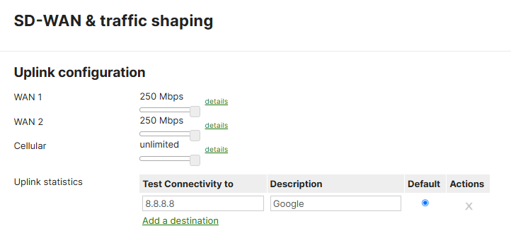
In the 'Uplink Configuration' section of the 'SD-WAN & Traffic Shaping' page, Meraki gives us the ability to set bandwidth limits for each WAN circuit - 250Mbps being the default. The 'Uplink statistics', an IP SLA feature, is a useful feature used to measure ICMP pings towards a specific destination IP address. If the object were to fail, Meraki's SD-WAN solution can failover to the secondary WAN circuit to maintain network uptime.
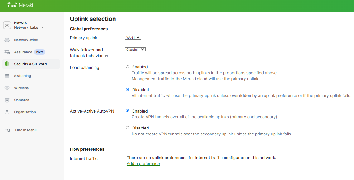
Uplink Selection
Features:
- Primary Uplink
- WAN Failover & Failback Behavior
- Load Balancing
- Active-Active AutoVPN
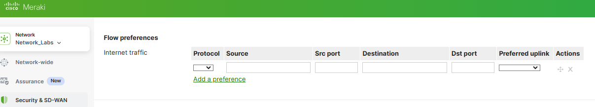
- Flow Preferences
In the Uplink selection section, you can specify the global primary WAN link for the entire Meraki network. In this section, you can also enable WAN link load balancing to split network traffic across both WAN links if desired. AutoVPN is a Meraki proprietary feature that enables Meraki WAN appliances to build VPN tunnels with one another located across separate network branches with just a few clicks. With Flow preferences, you can direct traffic matching a layer 3 parameter such as a protocol (UDP/TCP), and a source or destination IP address or port number out a particular uplink. Per Meraki's documentation, ICMP traffic is not subject to traffic shaping rules and as a result, flow preferences will have no impact on ICMP traffic.
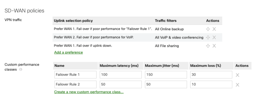
SD-WAN Policies
Features:
- SD-WAN Policies
The SD-WAN policies section appears after Acive-Active AutoVPN is enabled. Meraki's SD-WAN policies are essentially SD-WAN for VPN traffic. Per Cisco's documentation, in the case where there are redundant WAN uplinks configured on the MX appliance, traffic flows based on the type of traffic traversing the VPN connections can be configured to allow for the best performance. Custom policies can be configured to set desired baseline preferences to ensure traffic flows take the appropriate VPN uplink path.
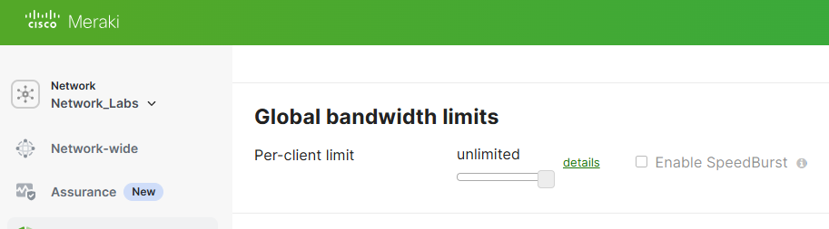
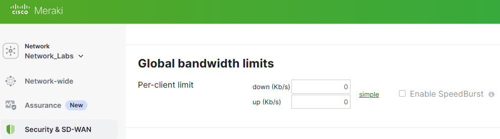
Global Bandwidth Limits
Features:
- Per Client Bandwidth Limit
With Global Bandwidth Limits, this setting allows you to put limits on each client device's total incoming and outgoing network traffic. With the Speedburst feature, Speedburst allows users to exceed their assigned limit in a 'burst' for a short period of time. Per Cisco's documentation, users are allowed up to four times their allocated bandwidth limit for a period of up to five seconds.
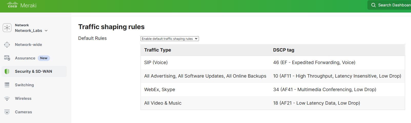
Traffic Shaping Rules
Features:
- Traffic Shaping Rules
With Meraki's Traffic shaping rules, it allows us to create shaping policies to apply to all users on the network on a per-application basis. Traffic shaping allows the reduction of the bandwidth for non-critical applications, and to prioritize bandwidth for business-critical applications. Per Cisco's documentation, Traffic shaping rules also apply to all traffic sent over a AutoVPN tunnel between Meraki devices but does not apply to traffic that passes over a non-Meraki VPN tunnel.
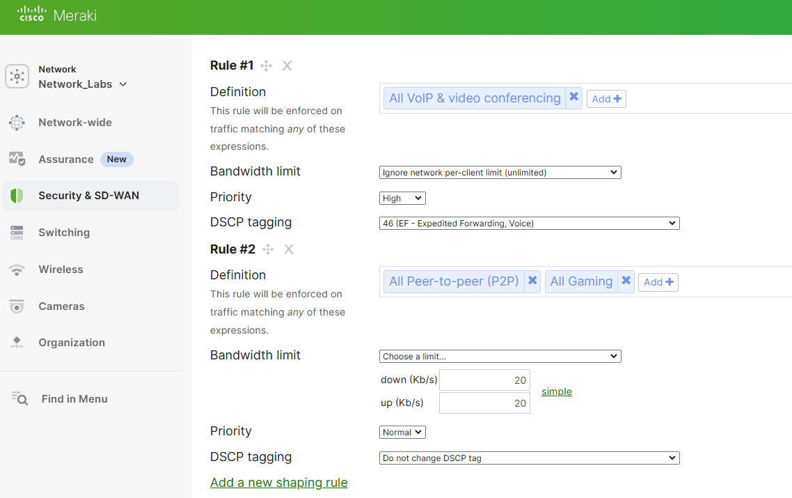
Sample Traffic Shaping Rule
The sample traffic shaping rule prioritizes VoIP traffic while minimizing peer to peer and gaming traffic down to 20Kb/s.
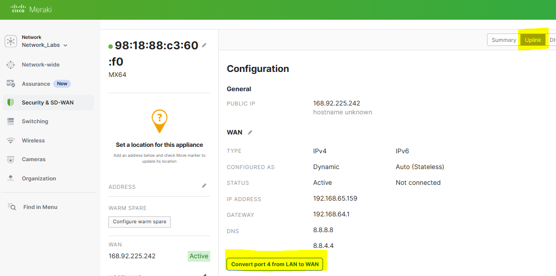
Configuration - Backup WAN Circuit
Scenario:
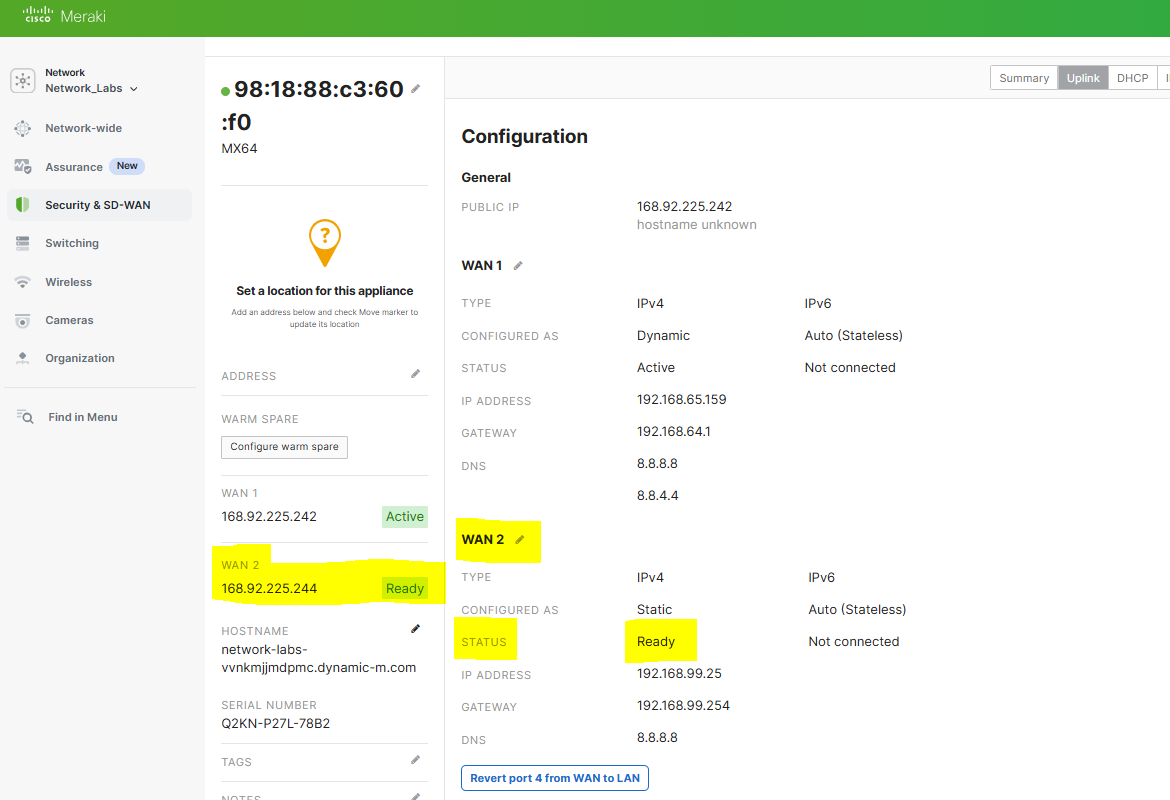
- In this lab exercise, to fully test SD-WAN in the next section, I will define a backup WAN circuit and designate this selection to the secondary WAN port '4' of the MX firewall
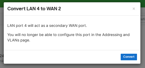
Menu to configure secondary WAN Port
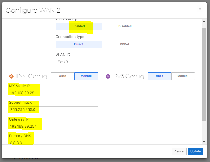
Configuration of the secondary WAN link parameters. In a real world scenario, the IP address assignment for a WAN circuit would be a publicly routable address. In this lab example, as I only have a single ISP circuit in my use case, I'm also using a Raspberry Pi serving as a secondary default gateway for the Meraki network that's bridging my wired Meraki LAN network wirelessly towards my ISP router behind NAT on a different subnet. This would allow me to simulate a secondary WAN device/network
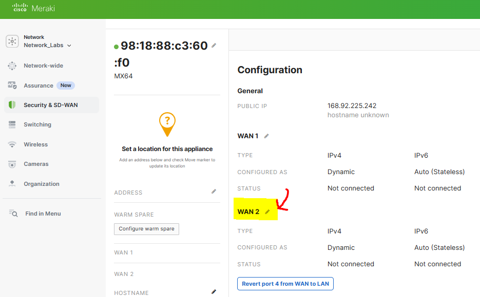
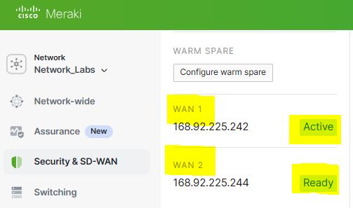
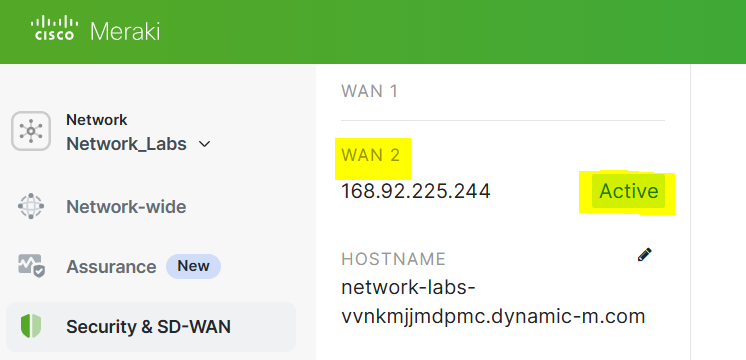
Verification of the secondary WAN link in a connected state
Configuration - SD-WAN Uplink Failover
Scenario:
- In this lab exercise, I will trigger SD-WAN to automatically swap the primary WAN link over to the secondary WAN link by creating a failover scenario on the primary WAN link 1
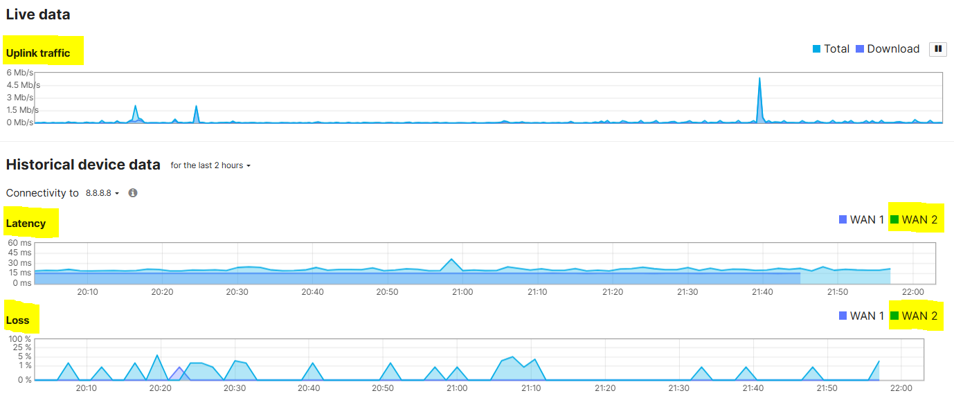
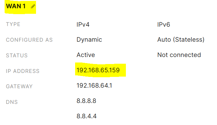
Verification of the redundant WAN uplinks in a 'Ready' state
Verification of VLAN80 client configuration prior to Uplink failover
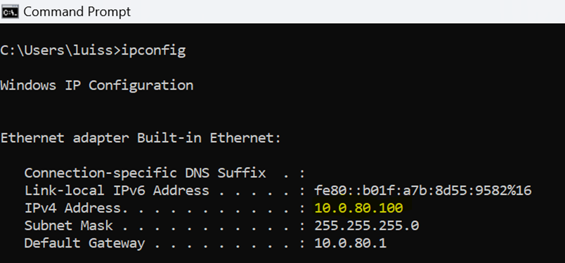
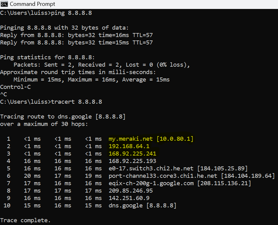
Client taking the primary uplink via device at IP address 192.168.64.1
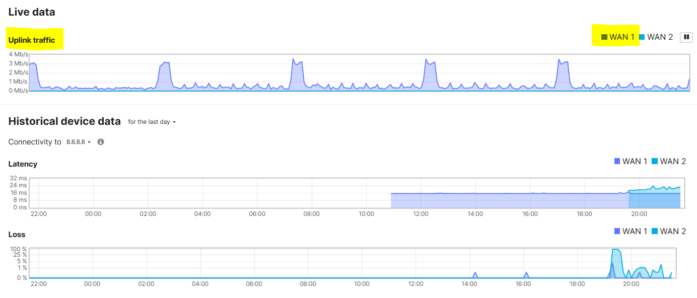
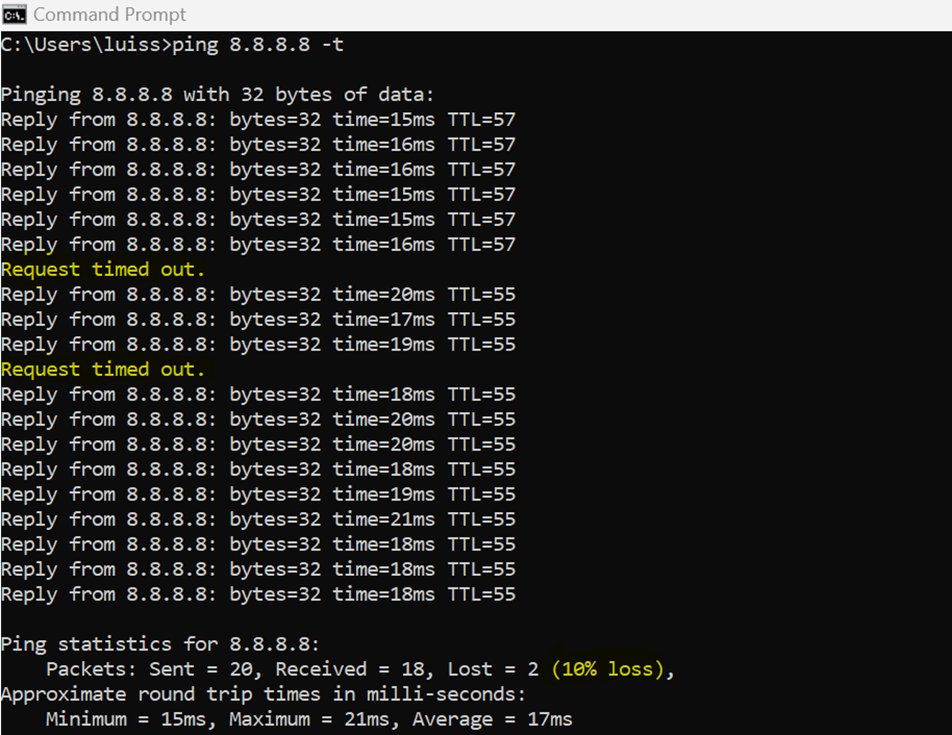
VLAN80 client failing over to the secondary WAN uplink by showcasing a continuous ping dropping a few ICMP packets after unplugging the primary WAN Ethernet cable on the MX security appliance
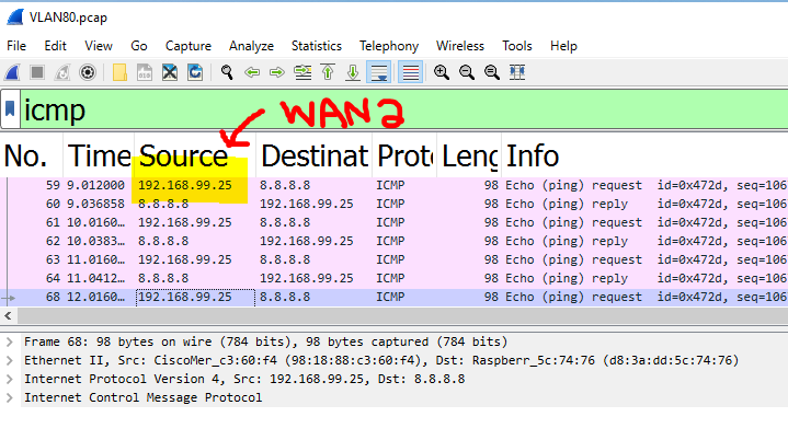
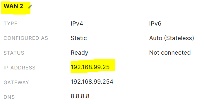
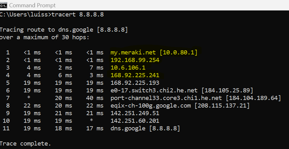
Client taking the secondary uplink via device at IP address 192.168.99.254
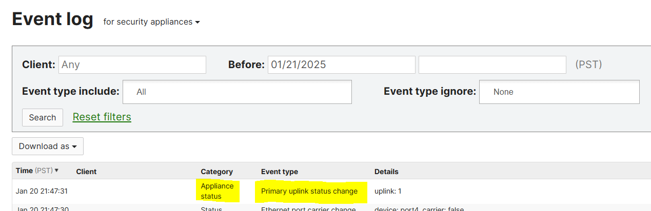
Verification of the Uplink failover event in the Meraki Event log via Meraki Dashboard
Configuration - SD-WAN Flow Preferences
Scenario:
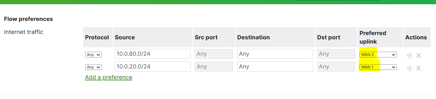
- In this lab exercise, I will demonstrate the SD-WAN Flow preferences feature by directing traffic out a particular WAN uplink based on source IP addresses on the network. In this example, traffic from the VLAN80 network will traverse through WAN uplink 2 whereas VLAN20 will take Uplink 1 as its preferred circuit
Flow Preferences Configuration
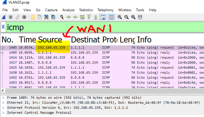
Verification of the VLAN20 10.0.20.0/24 network taking the WAN 1 Uplink. Traffic is sourced from the MX WAN IP Address
Verification of the VLAN80 10.0.80.0/24 network taking the WAN 2 Uplink. Traffic is sourced from the MX WAN IP Address