Monitoring Network Wide Topology
Sections:
Resources:
Overview:
- In Cisco Meraki, the monitoring Topology page is a feature that provides a visual representation of the devices and their connections within the Meraki network
- It allows you to see how devices are interconnected and provides insights into the network's architecture
- This page is particularly useful for network admins because it provides a centralized view of the entire network, helping to quickly identify issues, optimize configurations, and ensure the network is functioning as intended
Topology Overview
Topology Page Menu

Network Wide Topology
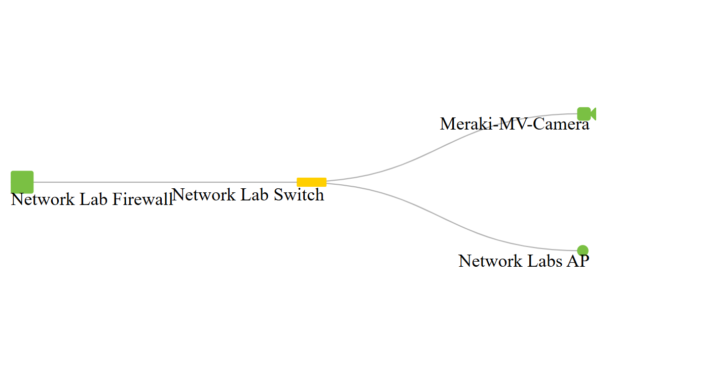
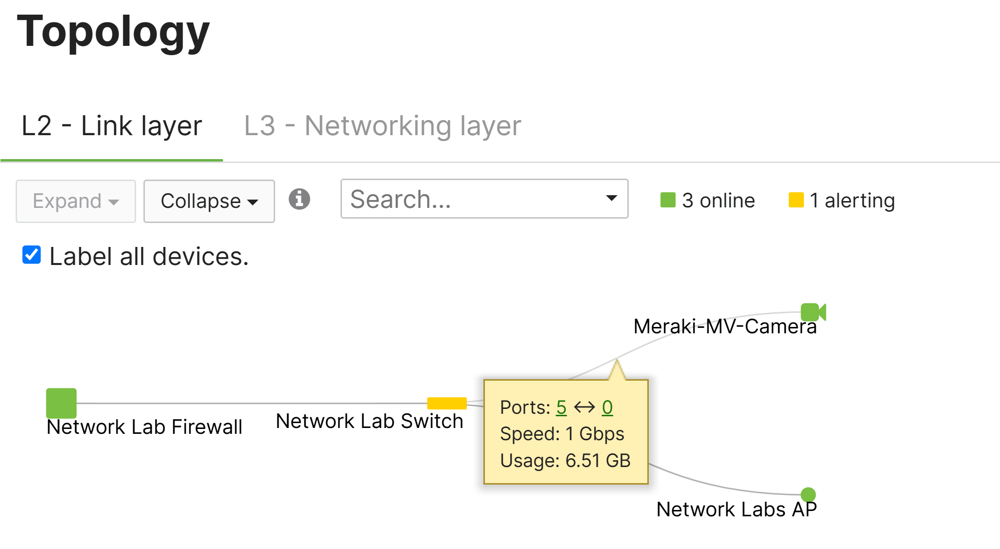
- To better understand the device legend icons used for the Topology page, squares represent MX security appliances, rectangles represent MS switches, and circles represent MR access points
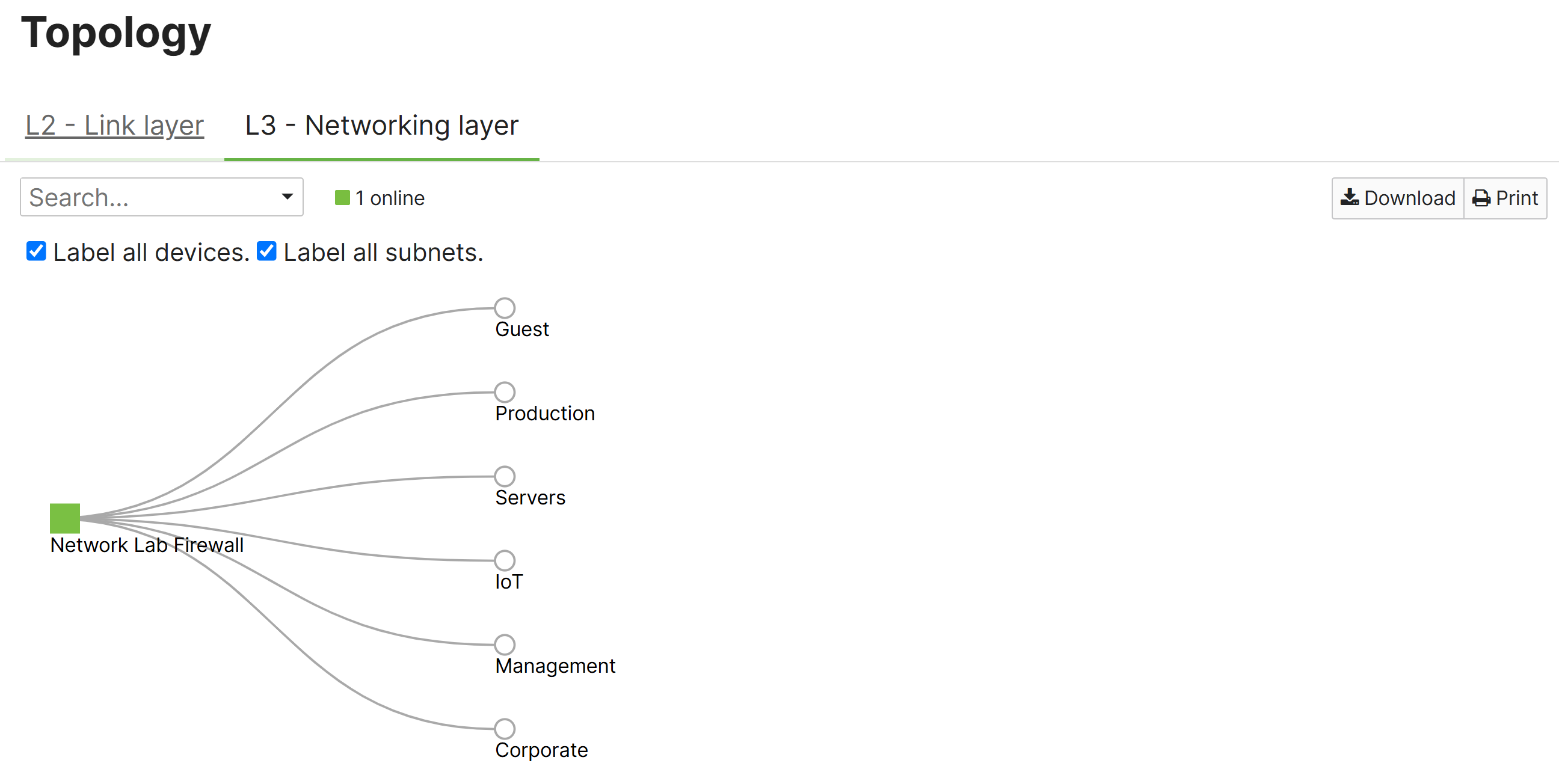
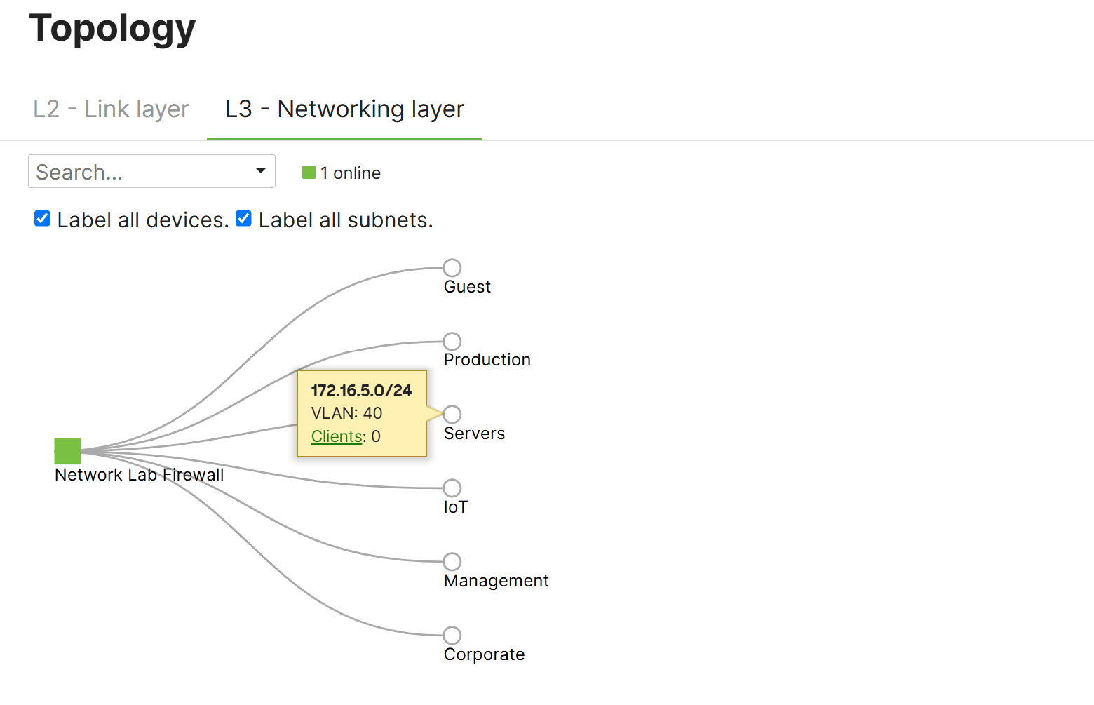
- In a Layer 2 Topology view, hovering over individual network links or nodes will display statistics about that connection's speed, usage, errors, and number of active connected clients whereas Layer 3 links and nodes will display subnets, node IPs on each specific subnet, VLANIDs, number of clients in the VLAN, and static routes for that particular node
- The Topology page can also be used for troubleshooting by visualizing nodes that are connected to each other, streamlining the identification of node misconfigurations if their are no visual connection between nodes
Important Cisco Notices
- Per Cisco, non-Meraki equipment is also detected in the Topology view if the device is one hop away (and will appear as an empty diamond); depending on the protocols supported by a non-Meraki device. The topology view may be able to discern LLDP data like model type, IP, and manufacturer
- Per Cisco, if an upstream core/aggregation switch in the network is not a Meraki MS switch and is capable of both CDP and LLDP, topology may not display correctly. To resolve this issue, it is recommended to disable CDP on the non-Meraki switch's interfaces to the MS switch or switch stacks. Once disabled, topology will slowly correct itself as the LLDP information is updated by each node
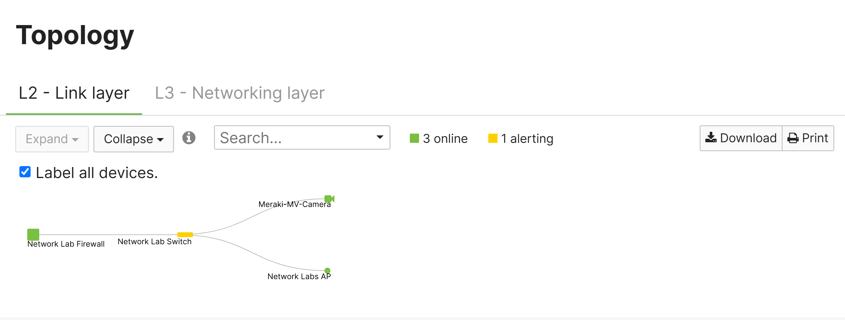
Layer 2 - Link Layer Topology
Layer 3 - Network Layer Topology
Layer 2 - Hovering Key Statistics
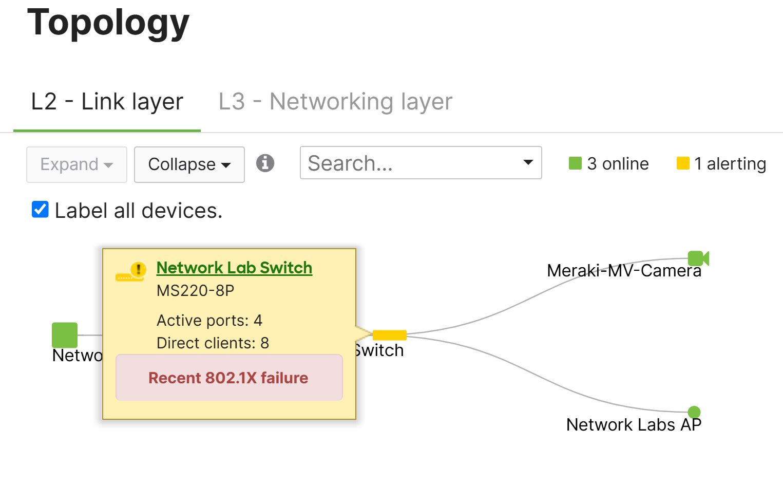
Layer 2 - Hovering Key Statistics
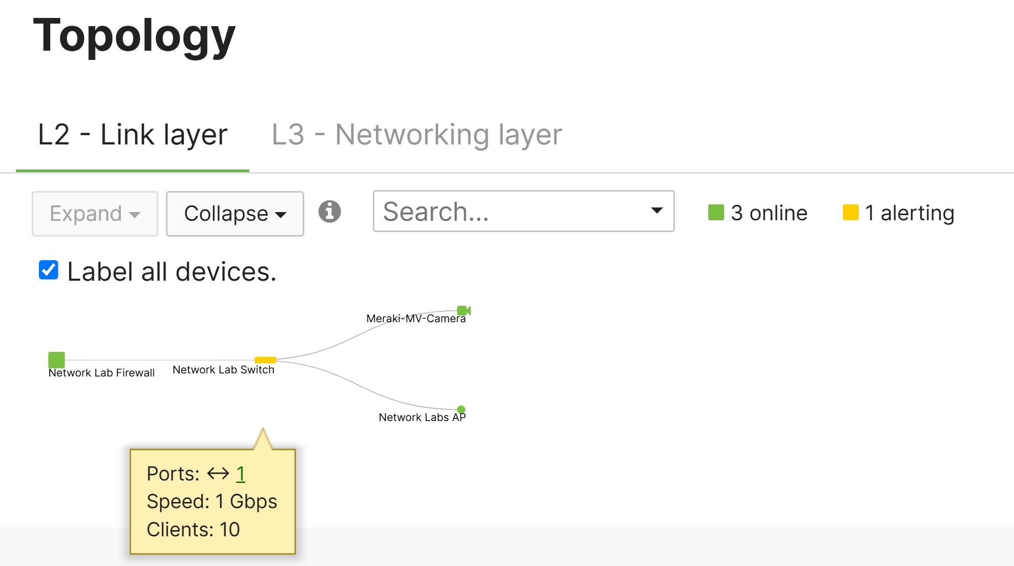
Layer 2 - Hovering Key Statistics
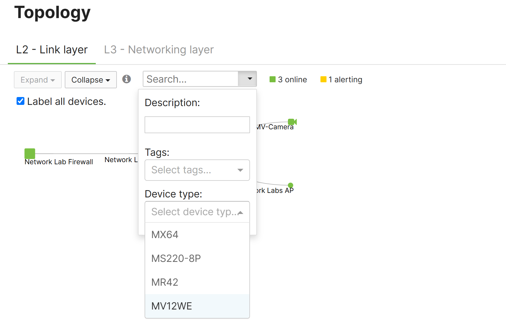
Layer 2 & 3 - Search Feature
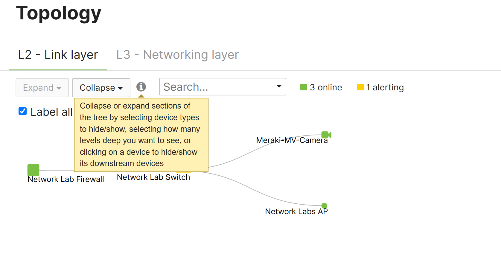
Layer 2 - Collapse Feature by Device Type
Layer 3 Topology Legend

Layer 3 - Hovering Key Statistics
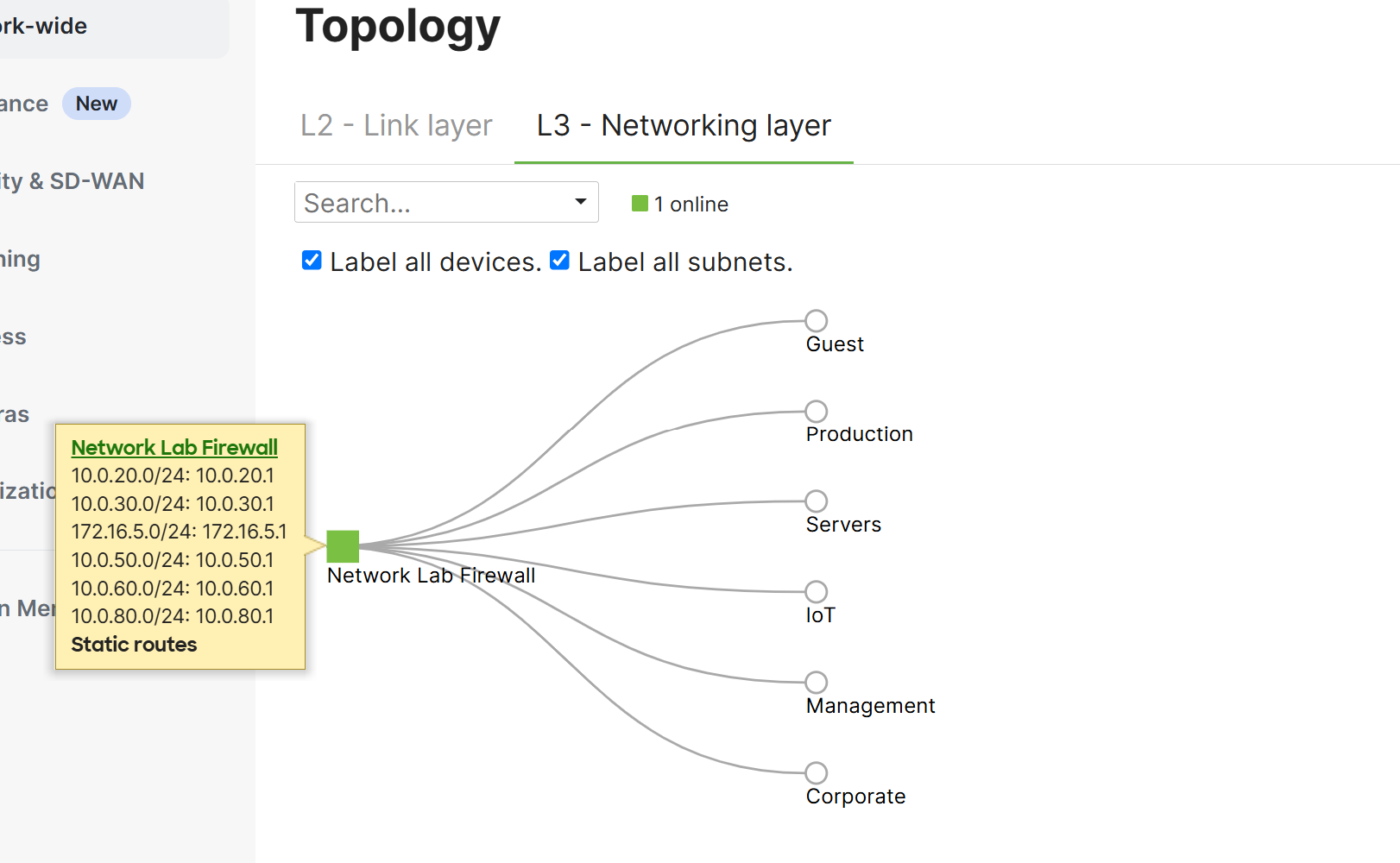
Layer 3 - Hovering Key Statistics
Download/Print Topology Feature

Downloaded Topology Page